Thanks for pointing that out. Perhaps the reduction of S/N ratio going from RCA coaxial to XLR is only an issue with an analog signal. With a digital bitstream, the signal is "all or nothing" so perhaps there is no loss of information.
Here is the post that triggered my confusion, from much earlier in the thread (3 years ago!):
The digital output on the P-965 looks like an RCA-type coaxial connector. I can't find any specifications regarding impedance or data format in the owner's manual.
Here is the post that triggered my confusion, from much earlier in the thread (3 years ago!):
"XLR Post #101 "
The digital output on the P-965 looks like an RCA-type coaxial connector. I can't find any specifications regarding impedance or data format in the owner's manual.
Oops, I still haven't figured out how to quote other posts. Let me try again.
"2-Converting "RCA to XLR ins" is no that easy. You need to apply gain by the same amount.Either electronically with an active gain stage or using good quality transformers. That's going to be more expensive.
You can live without increasing the gain, but your signal to noise ratio will suffer almost 12 db!
Hi Java,
separate digital from analogue.
Let's just consider digital into DCX2496.
The spec says it will accept 0.3Vpp to 10Vpp into approx 110ohms at the XLR balanced input. It also says it is compatible with S/Pdif and aes/ebu. That means any S/Pdif or aes/ebu digital signal can be sent to the DCX. The voltage level of the bits arriving will not affect the Signal to Noise ratio, so forget that 12db loss. If the DCX fails to lock on or cannot understand the datastream then nothing comes out. The problem could become intermittent locking on, giving a broken up output (that will sound terrible).
Now consider DCX analogue input.
The analogue signal into DCX is critical to signal to noise ratio and to distortion performance.
The input amplifier in the DCX can be adjusted through the range -15db to +15db. But the maximum input signal is +22dbu (about 9.75Vac) and to make full use of the S/N available you should try to get as many of the LED indicators to light up without the red peak LED lighting up. This effectively requires a minimum level (with +15db gain) of 1.73Vac when the signal is at MAXIMUM level. This just about suits CD which would require the gain to be set at +13db for a 2Vac CD output or +12db for a 2.3Vac maximum input.
The maxima from other sources will need external amplification (gain) to reach these levels.
However, I set my CD input to +8db for a 2.1Vac maximum and sometimes the red LED lights. There is something odd happening with the analogue gain. The manual says that earthing the cold pin adjusts the input and output amplifier gains but I have not quite understood what is happening (yet!).
Once you have the processing underway the signal comes out as an analogue +22dbu signal and should use EXTERNAL attenuation to adjust the volume, just as your point 1) said.
Some threads here show alternative internal output stages that remove much of the DCX final gain in a search for greater fidelity and they just happen to give an output that particularly suits domestic signal levels.
The slightly unfortunate ability of the DCX inputs is taking either digital or analogue or microphone signal and adjusting the internal routing to suit the signal , all from the same XLR balanced sockets. Very confusing.
Janneman and some other German guy have a very good handle on the internal workings of the DCX.
Hope this helps rather than adding to the confusion.
Hi guys,
I bought a DCX2496 a week ago.
On the enclosure it states 0607
So this unit was assembled in July 2006.
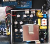
I opened the enclosure and made a few pictures, so that those of you with experience can detect possible differencies with older production units.
I am still wondering whether to replace the analogue out board with that designed by Jan Didden or the one on the Selectronic site (who will come also with a new high-end design)...
Regards,
Lucas
I bought a DCX2496 a week ago.
On the enclosure it states 0607
So this unit was assembled in July 2006.
I opened the enclosure and made a few pictures, so that those of you with experience can detect possible differencies with older production units.
I am still wondering whether to replace the analogue out board with that designed by Jan Didden or the one on the Selectronic site (who will come also with a new high-end design)...
Regards,
Lucas
Attachments

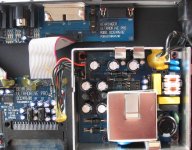
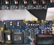
Seems that not much differences at least looked from the top
You can compare to my pics from a few years ago
http://f5.infonet.ee/ergo/DCX2496/dcx2496%20002.jpg
The transformer in power supply seems to have a shield in yours and also the serial communication ports have a shield in yours.
Ergo
You can compare to my pics from a few years ago
http://f5.infonet.ee/ergo/DCX2496/dcx2496%20002.jpg
The transformer in power supply seems to have a shield in yours and also the serial communication ports have a shield in yours.
Ergo
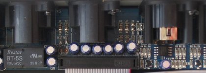
Yes, that's the latest version, I've opened one a few weeks ago.
There are minute differences compared to the "old" versions : SMPS
shielding, decoupling caps on the output opamps, slightly different
layout for the clock oscillators, all in all nothing major. By the way
Selectronic is launching a high-end ouptut stage for the DCX :
http://www.selectronic.fr/audiophiles.asp
The input XLR sockets aren't installed yet on this example but they'll
be Neutrik ones. It's a plug & play board which keeps all of the
original functions operating and improves A LOT the analog performance. Picture :
An externally hosted image should be here but it was not working when we last tested it.
Hi THMartin,
Will the final new board only ship with RCA cinch plugs outputs (as seen on that Photo) or can one choose for balanced XLR's?
Maybe you could be so kind as to translate this technical description into English, since I am sure many English speaking people will find it very interesting:
Certains choix ont été plus délicats à faire pour ce circuit que pour l'horloge ou l'alimentation DC. En effet, les modifications indispensables sont très délicates à effectuer pour un amateur non aguerri, car nous sommes ici dans une zone de CMS pur et dur. Par exemple, il faut éradiquer les 24 amplis OP de sortie qui n'ont plus d'intérêt ici et qui surchargeraient la nouvelle alimentation analogique si on les laissait alimentés...
Ceci d'autant plus que, sur le plan technique, récupérer le signal directement en sortie du DAC est en principe déconseillé par le fabricant dudit DAC, mais aussi parce qu'une une ESD (décharge électro-statique) destructrice est vite arrivée.
Enfin, nous n’oublions pas que le possesseur du DCX fait du "sans filet" vis à vis de la garantie de BEHRINGER !
En résumé, nous avons opté pour la version la plus sécurisante pour l'utilisateur et la plus transparente à l’écoute.
Notre kit:
La platine est du type PLUG & PLAY et vient s'insérer en lieu et place de la platine d'origine, sans aucune modification.
Elle comprend :
• Les 3 circuits d'ENTRÉE A, B et C qui reprennent le schéma BEHRINGER d'origine, mais avec des amplis OP "high end" et des condensateurs de liaison BLACKGATE là où ils sont nécessaires
N.B. : les composants des circuits d'entrées analogiques A , B et C sont optionnels. Le kit de base ne conserve que l’entrée NUMÉRIQUE et l’entrée MICRO.
• Les 6 circuits de sortie de notre conception qui présente l'avantage d'exploiter correctement chaque sortie symétrique du DAC et de respecter les impédances de charge (tout en passant totalement inaperçus puisqu'ils sont parfaitement transparents à l'écoute !). Mais l’utilisateur garde la possibilité de sortie directe depuis le DAC.
En outre, chaque sortie peut soit être directe (sans condensateur), soit avec un condensateur de liaison (au cas où) et possède un filtre réalisé au moyen de condensateurs au mica argenté.
• La platine de connexion des entrées et sorties audio utilisant nos embases RCA argentées isolées Teflon et de véritables connecteurs NEUTRIK
• Un véritable circuit de MUTE électrique (et non "logiciel") sans "cloc" lors des commutations utilisant des relais à contacts argent, alimentés par un circuit indépendant.
• Les sorties RS-232 et "LINK A et B" ont été conservées
• Des nappes d'interconnexion beaucoup plus courtes que celles d'origine et surtout de bien meilleure qualité ! (en effet, des mauvais contacts ont été constatés sur plusieurs appareils entraînant des comportements erratiques du DAC pouvant être dangereux pour le tweeter en particulier).
L'ensemble n'utilise que des composants discrets haut de gamme pour un câblage à la portée de tous.
Thanks in advance!
Regards,
Lucas
Hi Lucas,
I had a chat on the phone with Selectronic's boss this afternoon and I have good news :
- this page will be translated into english by next week
- Selectronic is about to distribute it's products in North America via Audio Express Magazine very soon.
Stay tuned !
Thierry
I had a chat on the phone with Selectronic's boss this afternoon and I have good news :
- this page will be translated into english by next week
- Selectronic is about to distribute it's products in North America via Audio Express Magazine very soon.
Stay tuned !
Thierry
At Selectronic they have different clock modules for the DCX at different frekvensys,What frekvensy to use.And isn´t it true that it uses the clock in the CD player via the S/PDIF cable,so no need to uppgrade the DCX clock or?
Hi Ryssen,
The frequency for the DCX is 24,576Mhz.
The other frequencies are for various CD player brands and models.
For the rest of your question you may want to read this : Digital audio Interfaces
Thierry Martin
The frequency for the DCX is 24,576Mhz.
The other frequencies are for various CD player brands and models.
For the rest of your question you may want to read this : Digital audio Interfaces
Thierry Martin
Thmartin said:
- Selectronic is about to distribute it's products in North America via Audio Express Magazine very soon.
Oops !
🙄
I've been too fast on this one : kits shall not be distributed via Audio Express which is only a magazine.
They'll be most likely sold by a specialized U.S. distributor.
Sorry if anyone has been misleaded.
Thierry
I will read that thanks!http://www.tnt-audio.com/clinica/diginterf2_e.html
I did a translation on:http://www.selectronic.fr/audiophiles.asp at Altavista,and it sead that you had the option to use the output with or without capacitors how is that possible.And is it possible to have the unit with XLR connectors at the output?Does the RCA come with the kit?Looks like an interesting alternative.Is there a schema of the unit on the web?🙄
Hi Ryssen,
Be patient for a little while, all of this is being finalized, including the translation 😉
Thierry
Be patient for a little while, all of this is being finalized, including the translation 😉
Thierry
DCX2496
Hi Jan,
As a new member I can't send you an email, so try it this way, although this might be wrong (have no experiance with forums so far).
I read your article about the DCX2496 mod in the audioXpress magazine. Brilliant idea!
I'd like to use your mod with UcD 180/400 amps from Hypex www.hypex.nl (balanced 100k inputs, also usable unbalanced with one input grounded, do not want to use the the Hypex DC filter because of sound quality, but to use the DC filter in your circuit).
My problem is to implement a 10k log volume potentiometer. I got one from Alps: ALPS 6-gang motorized Potentiometer RK16816MG 10KDx6 GB.
Do you have an idea how to integrate the poti. I would need several of your PCBs.
Thanks a lot.
Re: DCX2496
Hi Oettle,
Thanks for your kind words.
Assuming that you want to use this sechs-gang-poti for six single-ended channels, the easiest way is to use just one polarity of each of the six balanced outputs of the DCX (XLR pin 2 IIRC). Just connect the top of each pot to this pin, and the wiper to your amp.
You will most probably have a close proximity of the poti stuff to the DCX so you wouldn't miss the balanced advantage for low RFI etc which materializes only for longer cable runs anyway.
Alternatively, you could mount a bracket with 6 RCA jacks in the existing DCX holes and hard-wire them to the pcb. Then connect the hot RCA pin to the top of the pots.
Are you going to control the pots remotely?
Jan Didden
oettle said:[snip]My problem is to implement a 10k log volume potentiometer. I got one from Alps: ALPS 6-gang motorized Potentiometer RK16816MG 10KDx6 GB.
Do you have an idea how to integrate the poti. I would need several of your PCBs.
Thanks a lot.
Hi Oettle,
Thanks for your kind words.
Assuming that you want to use this sechs-gang-poti for six single-ended channels, the easiest way is to use just one polarity of each of the six balanced outputs of the DCX (XLR pin 2 IIRC). Just connect the top of each pot to this pin, and the wiper to your amp.
You will most probably have a close proximity of the poti stuff to the DCX so you wouldn't miss the balanced advantage for low RFI etc which materializes only for longer cable runs anyway.
Alternatively, you could mount a bracket with 6 RCA jacks in the existing DCX holes and hard-wire them to the pcb. Then connect the hot RCA pin to the top of the pots.
Are you going to control the pots remotely?
Jan Didden
- Home
- Source & Line
- Digital Line Level
- Behringer DCX2496 digital X-over