danielwritesbac said:
I'm not a guru, and this thread is "by request." In fact, I didn't start this particular thread until getting some help from Mr. AndrewT, to confirm the grounding circuit. Please consider my role in this thread as like a "translator." We have Gychang's group here, all suddenly building amplifiers. 😉
Their soldering irons are hot and they're ready to go, and then. . .
Reference this Schematic:
An externally hosted image should be here but it was not working when we last tested it.
Hi.
You might want to mention where you took that schematic from. 😉
This ground loop breaker may not be needed. Why not stick with the important stuff before getting bogged down in specific cures for problems that may not exist?
seventenths said:Can you explain this please?
Thank you.
7/10
That's in regards to:
danielwritesbac said:There is no effective power without an sufficiently strong reference, and that reference is the ground. Lets do both well. 😉
No ground example:
Birds sitting on power lines are without a reference to ground. They receive neither voltage nor amperage.
That's fantastic for birds, but terrible for speakers. A "questionable" ground is also bad for speaker performance.
Power goes into and out of speakers:
The more power you put into speakers, then the more power is returned into the zero volt line. Therefore, you can see why it should have strength.
The AC signal (audio signal) that is returning from the speakers does feed right into the power supply; however, the power supply is supposed to stay at DC. That's a problem because any amount of voltage on the zero volt line does decrease available power output. And, that's a problem because AC on any DC line is noise.
For good speaker performance (electronic dampening topic), the usual fix is "the path of least resistance" and, simply put, that's a very strong ground system.
So, that's why I started the thread with Safety Earth Grounding--both to avoid shocks in the UK, and yes, also to avoid the potential for "bass shy" issues as well. The ground, often overlooked, is equally, if not more important, than the power. Sometimes, and especially in the UK, it needs some help. That help is provided on an "as needed" basis by the strong diodes in our ground loop breaker / safety disconnect network.
And, quite frankly, its the best I can do.
MJL21193 said:Hi.
You might want to mention where you took that schematic from. 😉
This ground loop breaker may not be needed. Why not stick with the important stuff before getting bogged down in specific cures for problems that may not exist?
Hi John!! I'm so glad you're here.
Okay first,
Rod Elliot has that schematic on his website.
And, second,
My favorite amplifier from the 70's was always a bit loose on the bass, so as an experiment (I'm not advising it!), I plugged the disconnect network into the ground port, and the other end to earth ground. On the second try, the experiment worked as intended, and rocked down the house with really slammin' bass.
It was the first time in over twenty years that the old amplifier had such a performance.
So, I think its important. I think that I verified it useful, and I think we need a fuse too. 😉
What do you think?
danielwritesbac said:
On the second try, the experiment worked as intended, and rocked down the house with really slammin' bass.
It was the first time in over twenty years that the old amplifier had such a performance.
So, I think its important. I think that I verified it useful, and I think we need a fuse too. 😉
What do you think?
I think that this is just nonsense. That loop breaker cannot do what you say, nor is it intended to to. You drift into the land of mumbo-gumbo again when you make such ridiculous claims.
If you build an amp and the bass is weak there is something wrong. Any good amp is designed to amplify the entire audio band accurately.
You may have used the wrong values for some components (increasing the low end cut off frequency). There could be any number of causes.
MJL21193 said:I think that this is just nonsense. That loop breaker cannot do what you say, nor is it intended to to. You drift into the land of mumbo-gumbo again when you make such ridiculous claims.
If you build an amp and the bass is weak there is something wrong. Any good amp is designed to amplify the entire audio band accurately.
You may have used the wrong values for some components (increasing the low end cut off frequency). There could be any number of causes.
Thanks man! I take that as a clue to "move on" and build the power supply board.
Will do.
P.S. You guessed right on the cutoff frequency thing! How did you know? That was Technics SA80, with cutoff frequency at 45hz. It had been suffering "jukebox bass" but it no longer has that problem. Previously, it (and its cousins also in my collection) had a slight voltage at the metal front panel. That problem is gone too.
It seems that the "something wrong" that you mention (above quote) can happen to both professionals (Technics/Panasonic) and amateurs (Me) alike.
EDIT: There's a great clue!! I think that we should measure voltage of metal parts before touching them with fingers. I had never tried that with my commercial audio equipment before. Now, I learn that I shouldn't have assumed. . . I should have checked years ago. Maybe that would have prevented my mysterious turntable explosion in 1993?
POWER SUPPLY
If you have an Audiosector PCB or the style of "open wire" (no pcb) that has similar large caps right on the board, then this (pictured) is all you need for a power supply board.
The parts are a 1 piece rectifier (KBPC1004 or KBPC1005) along with 10nF caps (ceramic or polyester).
These 10nF (0.01uF, "103") little caps subtract rectifier noise, which reduces heat and reduces radio interference.
Also, have a look a photo # 4 in Mark Houston's design http://www.diyaudio.com/forums/showthread.php?s=&threadid=123515 and you'll see this same thing.
I like this little plastic rectifier (KBPC1004), because the top of it is clearly marked for hookup.
Attachments

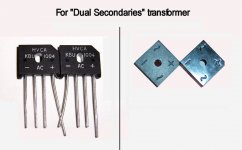
What if your transformer has 4 wires coming out instead of 3?
That would be a dual secondaries transformer. In that case, you use two rectifiers.
The AC terminals are marked on both the transformer and the rectifiers.
The DC output of the rectifiers go just like flashlight batteries in a 2-cell flashlight (- + - +). The centrepoint between the two is the 0V line. See photo.
Attachments
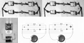
Here's a photo montage that takes the mystery out of how to deal with two rectifiers (for use with dual-secondaries transformers).
This is quite similar to hookup methods for the Audiosector and Chipamp.com power supplies.
Maybe the photo will help to explain them.
This is quite similar to hookup methods for the Audiosector and Chipamp.com power supplies.
Maybe the photo will help to explain them.
Attachments
What if we have an amplifier board that doesn't have large (1500uF or so) caps onboard?
Our recent LM1875 project uses one of these values on the amplifier board:
220uF
330uF
470uF
And so we can tell from this, that we need both rectifier and a full power supply board to go with it.
Here's a commercial example:
http://www.electronics123.com/s.nl/it.A/id.347/.f
But, I think that we can do better, without spending more. Before we do, have a look at the documentation for this one: http://electronics123.net/amazon/datasheet/k114.pdf
There's actually a lot of variety in power supplies, but they do have a few things in common.
First, the caps that are directly at the rectifier are exposed to rectifier noises and they get warm. In the commercial example above, the caps on the right side (first line of defense) get warm.
After the first pair have worked hard to make relatively clean power, then the second pair run cool.
That's working like this:
1). Transformer
2). Rectifier (diodes)
3). Caps that clean the power
4). Caps that contain a clean reserve, similar to a battery
Here's a larger example:
Look closely and see that a pair of 3300uF are cleaning the power before passing on to a pair of 10,000uF, and the 10,000uF are then able to provide clean reserves for the amplifier.
Attachments
I have NEVER felt nor measured ANY smoothing caps that get warm. Mine ALWAYS stay cold even with big ClassA & ClassAB power amps hanging off the supplies.danielwritesbac said:First, the caps that are directly at the rectifier are exposed to rectifier noises and they get warm. In the commercial example above, the caps on the right side (first line of defense) get warm.
I wonder why a chipamp would do this to your's? Seems very odd!
AndrewT said:I have NEVER felt nor measured ANY smoothing caps that get warm. Mine ALWAYS stay cold even with big ClassA & ClassAB power amps hanging off the supplies.
I wonder why a chipamp would do this to your's? Seems very odd!
Oh, they're not hot. They're just slightly warm. I had to measure to find out.
I'm trying to establish a theme here, and using that little commercial board as an example, presented the idea of "first line of defense."
So, I'm hoping to explain why some nice fast caps at the rectifier, can be a good thing to just get the job done on clean DC.
Of course, there's a lot more concepts to power supplies, but if I have to choose. . . clean DC is important. 😉
Here's another concept that I believe to be important. . .
I think that speaker support vs cap speed can give us a clue about the minimum size caps to use.
The ground return of your speaker hooks to the zero volt line (Power Star Ground). Therefore, I'd hazard to say that the minimum size power supply capacitor is exactly the same size that could possibly pass the entire audio signal if used for a crossover.
Popular examples include 1500uF, 2200uF, and 3300uF.
Simply put, the centrepoint figure is 2200uF, so let's use it for the "first line of defense," right at the rectifier.
A 2200uF 50v cap is quite inexpensive and fits easily to a variety of projects. Its usually fast enough to do a great job for clean DC (power smoothing). Its also large enough for reserves, but that could be expanded. . .
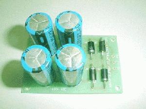
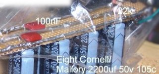
The simplest way to expand on a pair of 2200uF is to add 3 more pairs of 2200uF (in the photo below).
The total number of 2200uF capacitors in the photo attached, is eight. If you price that, its a bargain. When you go to solder that, its a breeze.
Here's a sample photo.
Soon, I'll make another with a bit wider board and show the rectifier attached as well.
The total number of 2200uF capacitors in the photo attached, is eight. If you price that, its a bargain. When you go to solder that, its a breeze.
Here's a sample photo.
Soon, I'll make another with a bit wider board and show the rectifier attached as well.
Attachments
I don't agree wit hthe last post entirely...
Yes you get lower ESR from parallel caps.
However it is not economical....
In that you need more space (larger case = more money), also the price of paralled caps tend to at least equal and often exceeds the cost of one single larger unit.... At least for as long as I have been looking into it.
If you are going to use parallel caps make sure they can store the energy required to drive your load at x Watt.... some high school physics required to work out Joules...
Sometimes I will make a compromise and use 4700uf combined with 10000uf, I think there is some merrit to adding the faster (smaller cap)
If you want cap speed, put down the bucks for some Epcos Sikorels, will set you back about $50 each in $10000uF 63V. (nice and big they are 2 x 3 inch)
Also, you don't NEED two bridges for dual secondaries... it is merely an alternative, bringing its own cons...
Nordic said:I don't agree wit hthe last post entirely...
Yes you get lower ESR from parallel caps.
However it is not economical....
In that you need more space (larger case = more money), also the price of paralled caps tend to at least equal and often exceeds the cost of one single larger unit.... At least for as long as I have been looking into it.
If you are going to use parallel caps make sure they can store the energy required to drive your load at x Watt.... some high school physics required to work out Joules...
Sometimes I will make a compromise and use 4700uf combined with 10000uf, I think there is some merrit to adding the faster (smaller cap)
If you want cap speed, put down the bucks for some Epcos Sikorels, will set you back about $50 each in $10000uF 63V. (nice and big they are 2 x 3 inch)
Also, you don't NEED two bridges for dual secondaries... it is merely an alternative, bringing its own cons...
Well, I really like you, and please don't do the "cliffhanger ending" on such an interesting post. 😉
On pricing my power supply, it generally comes in around $10 to $14. And, its performance appears to be considerable. The main thing is that it can give the beginner a good solid baseline for some performance; and, do so in a simplistic and inexpensive way. This is, after all, a "very first build" project.
At this time, the space it takes up isn't a concern for me, considering the wooden amplifier enclosure is going to. . . 😀
I'm not prepared to spend $800 for smoothing caps for a pair of 300W into 4ohm monoblocks.Nordic said:......If you want cap speed, put down the bucks for some Epcos Sikorels, will set you back about $50 each in 10000uF 63V.....
Nordic said:will set you back about $50 each in $10000uF 63V.
AndrewT said:I'm not prepared to spend $800 for smoothing caps for a pair of 300W into 4ohm monoblocks.
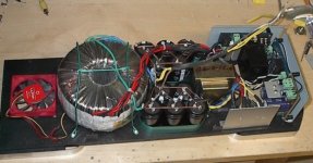
Yes, buying smaller caps in bulk quantities is more economical. For the same price quoted above, you could have 82,000uF (10 x 8200uf). Also, using smaller caps gives some flexibility for layout. I managed to squeeze everything in for this amp using smaller parallel caps.
Attachments
Dan -
I haven't had the time to follow either Peters or your threads as I'd hoped too.
When I 'glance in' I always have several questions and hope to get to them when time allows.
Of note today is that it would be nice to see 'sources' listed for parts as well as costs.
Also .... I bought RatShack boards that were copper imbedded. Wrong ones based on one of your threads? Those you'd mentioned by price were unavailable when I went there so need to know if I should exchange these for 'whatever' without copper for ease of 1st time build.
Thanks - Bluto
Bluto said:Dan -
I haven't had the time to follow either Peters or your threads as I'd hoped too.
When I 'glance in' I always have several questions and hope to get to them when time allows.
Of note today is that it would be nice to see 'sources' listed for parts as well as costs.
Also .... I bought RatShack boards that were copper imbedded. Wrong ones based on one of your threads? Those you'd mentioned by price were unavailable when I went there so need to know if I should exchange these for 'whatever' without copper for ease of 1st time build.
Thanks - Bluto
Yes, I'd exchange for "without copper."
For me, the pads just put conductors in all the wrong places, without much in the right place, so I spent a lot of time scraping.
Fortunately, I went with plain phenolic "perfboard" (no copper pads) on the LM1875 project, and that turned out much better. However, there was no question that it would.
At the Radio Shack, there's a postcard size phenolic board / perforated board--Catalog# 276-1394 or the larger Catalog# 276-1396.
To size "perfboard," just "score" both sides with a knife, flex back and forth, and it will pop cleanly in half.
- Status
- Not open for further replies.
- Home
- Amplifiers
- Chip Amps
- Beginner's Gainclone, Safety and, The Power Supply Board (please contribute)