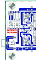
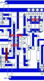
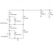
Yes, you have seen four transistor, but in real there are two bases (NPN II PNP) direct on input only, other pair are constant current source 300uA. On dipswitch you can find 100 Ohm; 470 Ohm and 47kOhm, 47p and 1nF. Phase shift is very important for real sense of music and 3D stage. This is not exist in OpAmp's configurations, maybe is a bit lower noise figure, but without any living. This is my opinion only.
There are eight bases in parallel: four NPN and four PNP. Two might be physically
closer to the input, but I don't think that matters, as they are all soldered to the same place.
If we leave just four input transistors, two NPN and two PNP, there are two LTPs at the input, with one resistor each to V- and V+ respectively.
Yes, you may use a dipswitch to select the right R//C combination, or you can simply solder them, eliminating four contacts.
Not that I was expecting you to agree 😀.
You are conflating two different issues: loading the cartridge (with the side effect of possible resonances in the audio band) and the optimum noise figure. These are different issues, both related to the cartridge (source) impedance.
As others have already mentioned, you don’t need a very precise MM model to address both issues. The DC resistance and the inductance are usually both specified in the MM cartridge data sheet.
Sorry, I didn't mean to antagonize with my disagreement.
You didn't agree with using 600R to ground, working as the cartridge load, if I got it right. Besides that there should be an inductance to put in parallel with that resistance, and that that data was specified in each cartridge data sheet.
The would be the way to get to a noise figure. Am I correct?
So I went to have a look at two reputable designs: one from Erno Borbely, in The Audio Amateur, and the other a mod made by Gary Galo on and Adcom preamp, which was based on a LT datasheet design.
None of them take noise into consideration, only the cartridges output level, to set the gain, and the LPs RIAA, to set the filters right.
But if I'm not wrong, the original Elektor article did raise the noise question, and why they used four transistors in parallel for NPN and PNP, exactly to lower the transistor's noise.
The specific cartridge specs should affect the input capacitor and resistor values, so them should be defined when those variables are known. It's not an opinion, it's a fact.
Building different preamps to listen to them is something I already planned beforehand, it's not my conclusion.
If you have a suggestion on how to improve the impedance modelling, please tell me how to do it or what values to use, and I'll try it.
But after solving that and getting to a more "realistic" simulation, it still remains the fact the sound quality of each preamp. The audible differences are what I'm interested in, and that we can't simulate.
If you like building preamplifiers and listening to them, just go ahead. I was under the impression that your remark about building several preamplifiers related somehow to the discussion we had about noise optimization. That's why I didn't understand you.
As was written earlier, the cartridge manufacturers usually specify the DC resistance and inductance of the cartridge. A simple LR series network with L and R according to the manufacturer's specs is good enough when you want to noise-optimize your amplifier.
That is, the thermal noise of the cartridge itself will be somewhat underestimated and the (typically huge) record surface noise will not be included at all, but that won't lead to a non-optimal amplifier design. It just leads to an overestimation of the difference in signal-to-noise ratio between an optimal and non-optimal design.
Because of all the frequency dependencies (frequency-dependent cartridge impedance, frequency-dependent gain, frequency-dependent ears), it will be a bit difficult to interpret the equivalent input and output noise density graphs. The usual solution is to put a noise weighting filter, like an A-weighting or ITU-R 468 filter, behind the amplifier and to look at the noise at the filter output over the full audio band. (That is, take the square root of the integral of the noise PSD over the audio band; LTSpice calculates that automatically when you ask for the noise over the band.) After dividing by the gain at 1 kHz, you have an equivalent integrated input noise that you can use to compare the noise performance of different designs.
A simpler alternative is to just look at the equivalent input noise density of the amplifier at 3852 Hz for RIAA- and A-weighting or at 5179 Hz for RIAA- and ITU-R 468 weighting. Under a couple of simplifying assumptions, such as negligible 1/f noise, it can be shown that optimizing the spot noise at 3852 Hz or 5179 Hz is equivalent to optimizing the integrated weighted noise.
Sorry, I didn't mean to antagonize with my disagreement.
You didn't agree with using 600R to ground, working as the cartridge load, if I got it right. Besides that there should be an inductance to put in parallel with that resistance, and that that data was specified in each cartridge data sheet.
The would be the way to get to a noise figure. Am I correct?
So I went to have a look at two reputable designs: one from Erno Borbely, in The Audio Amateur, and the other a mod made by Gary Galo on and Adcom preamp, which was based on a LT datasheet design.
None of them take noise into consideration, only the cartridges output level, to set the gain, and the LPs RIAA, to set the filters right.
But if I'm not wrong, the original Elektor article did raise the noise question, and why they used four transistors in parallel for NPN and PNP, exactly to lower the transistor's noise.
So let me understand correctly: you are suggesting to load a MM cartridge with 600 Ohm? That would be indeed an innovative approach. It would introduce a frequency dependency, that would potentially create an up to 40dB attenuation at the end of the audio band. Care to point me to a MM cartridge that recommends such a load?
BTW, the DC resistance and inductance of the cartridge are in series with the input. But obviously if noise is not of your concern then you could forget about any optimization.
Yes, you have seen four transistor, but in real there are two bases (NPN II PNP) direct on input only, other pair are constant current source 300uA. On dipswitch you can find 100 Ohm; 470 Ohm and 47kOhm, 47p and 1nF. Phase shift is very important for real sense of music and 3D stage. This is not exist in OpAmp's configurations, maybe is a bit lower noise figure, but without any living. This is my opinion only.

The figure is not visible in my computer. There seem to be two circuits you are discussing !
Shouldn't the inductance be in series with the DC resistance, as seen from the amp's input?You didn't agree with using 600R to ground, working as the cartridge load, if I got it right. Besides that there should be an inductance to put in parallel with that resistance, and that that data was specified in each cartridge data sheet.
Best regards!
Well, well, well. It turns out the anti-RIAA model is OK, with 604 ohms resistor and all.
http://hifisonix.com/wordpress/wp-content/uploads/2016/12/Accurate-Inverse-RIAA.pdf
And the 604R resistor is not a load for the cartridge, but for preamp.
And the circuit is intended to cut 44.1dB at 1KHz. It was designed by Lipshitz.
http://www.hagtech.com/pdf/riaa.pdf
To simulate MC cartridges the input load resistor changes to 50 ohms.
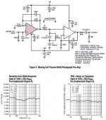
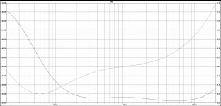
Below is the FR curve you get from the simulation. Note that the margins in dB and degrees for the phase are very very small, so both can be considered flat.
It's still pending what inductance to add to simulate noise.
In any case, the FR curve simulation you get is quite weird.
http://hifisonix.com/wordpress/wp-content/uploads/2016/12/Accurate-Inverse-RIAA.pdf
And the 604R resistor is not a load for the cartridge, but for preamp.
And the circuit is intended to cut 44.1dB at 1KHz. It was designed by Lipshitz.
http://www.hagtech.com/pdf/riaa.pdf
To simulate MC cartridges the input load resistor changes to 50 ohms.
Below is the FR curve you get from the simulation. Note that the margins in dB and degrees for the phase are very very small, so both can be considered flat.
It's still pending what inductance to add to simulate noise.
In any case, the FR curve simulation you get is quite weird.
Attachments
No, I am not suggesting to load the MM cartridge with 600 ohms. I took that anti-RIAA model from this thread and used it.
The question of those anti-RIAA models is something I have been trying to find out everywhere. Some did include inductance in series or in parallel.
Maybe you can help me get to a proper model.
I just cut the 600 ohm resistor away and adjusted the input voltage to get a realistic value after the input filter, like 7.5mV. For that input voltage, with BC550/BC560 and for +/-30v I got 1.7V at the output. THD is -111dB for 2nd order and -158dB for 3rd order.
I haven't yet tried it on the other RIAA simulations.
Do you know some cartridge's DC resistance or inductance values for me to add? Like a Shure V-15 for instance.?
I will be back as soon as I will get an understanding of what is the scope of your posts. Jumping from noise and cartridge loading to (anti)-RIAA and THD is not helping the discussion.

Maybe the intention is to make an all-in-one simulation testbench?
In any case, this is a reasonably accurate impedance model for a Shure V15-III cartridge and its 47 kΩ//450 pF load.
I don't quite understand what are the parts values.
Maybe the intention is to make an all-in-one simulation testbench?
Yes, that is definitely my intention, the only scope of my posts. I thought that was clear.
We need an accurate anti-RIAA input filter to measure THD and FR.
And to have an approximation to the noise, apparently I need some cartridge data to add before the anti-RIAA filter.
We need an accurate anti-RIAA input filter to measure THD
No, you don't. THD has little to nothing to do with the overall frequency response.
Values are in scientific notation, in F, H and ohm units.
Curious, what are R2 and R4 modelling?
I don't know, but I guess iron losses and to some extent skin effect losses of the coil of the cartridge.
In the 1990's a former colleague of mine measured the magnitude and phase of the impedance of a Shure V15-III cartridge using a fancy HP impedance analyser. The phase didn't approach 90 degrees for high frequencies, as it would with an ideal RL series network, but flattened out around 72 degrees. That means that there were more losses than just a fixed series resistance.
In 2013 I hand-fitted his measured results to the LRC circuit I posted earlier today (but without C10 and R5). It's not a real physical model where each component corresponds 1:1 to some physical effect, it's just a circuit that has nearly the same impedance modulus and phase as the cartridge had.
Last edited:
No, you don't. THD has little to nothing to do with the overall frequency response.
Values are in scientific notation, in F, H and ohm units.
Both are on scientific notation.
You need to null the RIAA influence to get an accurate simulation of what the input signal does, either in distortion or in frequency response.
The better the models, of the parts or groups, the better the simulation.
I can't see what you want to get at.
There have been several threads on RIAA models for LTSpice, so it is a real concern now that LPs seem to be coming back.
Last edited:
Yes, that is definitely my intention, the only scope of my posts. I thought that was clear.
We need an accurate anti-RIAA input filter to measure THD and FR.
And to have an approximation to the noise, apparently I need some cartridge data to add before the anti-RIAA filter.
It wasn't clear to me, but it is now. You are making it difficult by putting everything in one simulation testbench, but I think it can be done.
For simulating the RIAA response accuracy, one would normally use a low-impedance (preferably zero impedance) source driving the input. That's because the transfer from the stylus tip to the loaded output voltage of the cartridge is the cartridge manufacturer's problem, provided the recommended load impedance is used.
Hence, you would normally check the accuracy of the response without the impact of the cartridge impedance and check the accuracy of the input impedance.
However, instead of using a 0 ohm source, you can use a source with any other impedance and look at the ratio between the actual voltages at the amplifier's output and input, though, and the actual ratio between input voltage and input current for the impedance check.
For noise simulations, you need a reasonable model of the cartridge's impedance and preferably a weighting filter behind the amplifier (the weighting can be left out when you use my trick).
For distortion simulations, using a reasonable model of the cartridge's impedance would also give you the most accurate results, although I don't know whether the difference with a low-impedance source is noticeable in practical circuits.
All in all, I think the best solution would be a voltage source with an impedance model for a cartridge, then the preamplifier, then a model for the amplifier's load impedance, an ideal voltage follower and then a split into two paths: an anti-RIAA filter and a noise weighting filter.
For frequency response, you would take the ratio (or difference in dB) between the terminal voltages at the output of the anti-RIAA filter and the input of the amplifier.
For distortion, you would simply look straight at the output. You would need to adjust the input signal level depending on frequency.
For noise, you would integrate the noise at the output of the weighting filter and divide by the 1 kHz gain.
Voltage controlled voltage source, with a laplace transform to get the inverse RIAA. From that you can work further up. Google it, i don't have anything at hand to show how it is done as I'm not behind my PC.
Second post:
:: View topic - Using Laplace equations for inverse RIAA
Second post:
:: View topic - Using Laplace equations for inverse RIAA
First, there are two RIAA types, one classic, one RIAA new with new lower section. And there are many old curves too, which are different from these two. In RIAA filters constructions is very important to have two steps with passive filters between. The backloop type RIAA, active filtering, shifting the phase more and are cheap solution. The best idea will be RL (with inductors) type filters in front of classic RC. But step higher is also type with active (equal scheme) close loop amplifier, where phase shift is in few degrees only. Excellent sound, but there are complicate to finishing. This is far more influent in quality like low noise. Anyway you have more noise from vinyl and dust like thermal noise from transistors, where the best choice are multiple transistors in parallel, but unfortunately are complementary pairs unavailable.
DSP solution is funeral for living sound. (from analog to digital, then curves and digital to analog with many interpolations, you loose life in music and became Terminator)
.
DSP solution is funeral for living sound. (from analog to digital, then curves and digital to analog with many interpolations, you loose life in music and became Terminator)
.
It wasn't clear to me, but it is now. You are making it difficult by putting everything in one simulation testbench, but I think it can be done.
For simulating the RIAA response accuracy, one would normally use a low-impedance (preferably zero impedance) source driving the input. That's because the transfer from the stylus tip to the loaded output voltage of the cartridge is the cartridge manufacturer's problem, provided the recommended load impedance is used.
Hence, you would normally check the accuracy of the response without the impact of the cartridge impedance and check the accuracy of the input impedance.
However, instead of using a 0 ohm source, you can use a source with any other impedance and look at the ratio between the actual voltages at the amplifier's output and input, though, and the actual ratio between input voltage and input current for the impedance check.
For noise simulations, you need a reasonable model of the cartridge's impedance and preferably a weighting filter behind the amplifier (the weighting can be left out when you use my trick).
For distortion simulations, using a reasonable model of the cartridge's impedance would also give you the most accurate results, although I don't know whether the difference with a low-impedance source is noticeable in practical circuits.
All in all, I think the best solution would be a voltage source with an impedance model for a cartridge, then the preamplifier, then a model for the amplifier's load impedance, an ideal voltage follower and then a split into two paths: an anti-RIAA filter and a noise weighting filter.
For frequency response, you would take the ratio (or difference in dB) between the terminal voltages at the output of the anti-RIAA filter and the input of the amplifier.
For distortion, you would simply look straight at the output. You would need to adjust the input signal level depending on frequency.
For noise, you would integrate the noise at the output of the weighting filter and divide by the 1 kHz gain.
I am not sure if putting the anti-riaa filter AFTER the preamp and RIAA would be "realistic" for calling it somehow. On all reviews measurements I have seen the anti-RIAA is always applied at the preamp input.
Of course that in tests they also use an LP with an FR sweep track, incorporating the cartridge and disk surface distortion and noise into the picture. Which is what we are trying to simulate.
Perhaps what I was proposing is not the ideal thing, but I have seen very little about RIAA simulation in the web. Maybe because it was not important anymore.
Some ground theories about RIAA are in addition, one from book AD (courtesy Analog Devices), second from aplication manual Linear Technology. But the best you can find in Audio Cookbook from AD if you find somewhere or older PMI with special division SSM. There are also many sources in foot of first document. In reality is vinyl dead, you are not able to find some original best LP's, from analog times. There are new reprints from digital archives, worth nothing for me.
Attachments
In reality is vinyl dead, you are not able to find some original best LP's, from analog times. There are new reprints from digital archives, worth nothing for me.
The record pressing plant in my hometown can't guarantee standard lead times anymore because of the high demand for records, see Europe's vinyl pressing plant - Record Industry . They also installed a studio in which completely analogue recordings can be made for customers who don't want to have any digital signal processing in the recording process ( 01-07 Hapy Birthday Record Industry & Artone Studio - Record Industry ).
- Home
- Source & Line
- Analogue Source
- BC550 BC560 Very low noise RIAA