For first test I am using switching power supply (MW). Anyway, classical type toroidal transformer with proper capacitors (10,000uF) and maybe triple ripple filter will be excellent. Together with existing 100E/100uF inside every modul. Similar amplifier I am using for power amplifiers on VMOS (IRFP240/9240) or lateral Exicon (20N20) or SK/SJ. This MeanWell are good for LED illumination purpose.
About current in first pair. Normally is 1mA very good and in the peak of working point the transistors, second line 3mA (inverting), third 7mA and at the end 24mA. This is the right model to maintain transit frequency to be faster and faster for stable and non oscillating current feedback. But the main catch is in two feedback gain resistors, because you have very low impedance in inverting pair, so you need very high current for stability. And add the servo too, which came on this point also. If need, you can go 80V rail to rail or more, while transistors are capable to working on such high voltage, but with higher noise figure. This is good measure for direct driving power amps. In my case all power amps are compound style, RIAA preamp is in oposite emitter follower. In input stage is very important to all possible current go to base on first pair, not meaning impedance in term of input resistor to ground. This meaning health sound. I am bad in english and expressions, excuse me, please.
About current in first pair. Normally is 1mA very good and in the peak of working point the transistors, second line 3mA (inverting), third 7mA and at the end 24mA. This is the right model to maintain transit frequency to be faster and faster for stable and non oscillating current feedback. But the main catch is in two feedback gain resistors, because you have very low impedance in inverting pair, so you need very high current for stability. And add the servo too, which came on this point also. If need, you can go 80V rail to rail or more, while transistors are capable to working on such high voltage, but with higher noise figure. This is good measure for direct driving power amps. In my case all power amps are compound style, RIAA preamp is in oposite emitter follower. In input stage is very important to all possible current go to base on first pair, not meaning impedance in term of input resistor to ground. This meaning health sound. I am bad in english and expressions, excuse me, please.
Last edited:
now you got it....You have to inject a 600mV signal to compensate the input reverse-RIAA filter loss....
Have a look also at other inv.-RIAA-filters, e.g.
at one of the Paul-Kemble-webpages:
Yes. You have to increase to about 50-200mV at preamp input to get significant distortion. As you self wrote above, no cartridge will do that. The simulation with 6mV input is already more than provided by most MM pickups ....So we can increase the input level now to see where a preamp clips and what's the distortion at that level. Right?...
Last edited:
Joztom, please upload the schematic of your discrete MM/MC for me to simulate.
I have a RIAA preamp project designed by famous Erno Borbely for The Audio Amateur, unfortunately using complementary FETs that you can no longer find, and I wanted to try them with bipolar available parts.
The 2240/970 transistors you used are not made anymore, and you only find fakes. The first thing would be to replace them with BC550/BC560 on the simulation.
Borbely used two stages, as the drawing shows.
Attachments
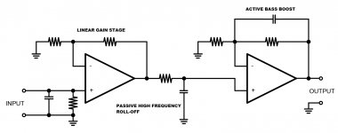
This implementation of passive LP and active bass boost might be the best choice of all possibilities for RIAA equalization. For an aqdditional 20 Hz roll off we might perhaps want to put a suitable capacitor in series with the bottom resistor of the 2nd opamp's feedback loop.
Best regards!
Best regards!
@carlmart. You are clever and understand my theory. It is hard to find mentioned pairs, but there are some 50 pairs in my stock. If need I will sell you some. I have my RIAA done from old LinearTechnology proposal for passive scheme, but I OPAMPs changed with my discrete construction OpAmp with SC/SK and BD medium power low noise on high current. I implemented servo with OP97 too for safety and brilliant tonal quality. If you are interested, I will send you a 1 copy of PCB with 4 pairs of mentioned High voltage low noise transistor but confident and with agree for no copying and for personal use only. There is a problem to change with BC550/560 in term of diferent BCE pins. Last week I tested in domestic HighEnd shop with success.
RIAA.pdf

RIAA.pdf
Attachments
Today I started to make further changes on the SLN, testing different voltages and also different complementary transistors.
The results I'm getting are surprising, interesting and exciting. My findings concentrated on THD simulations with LTSpice.
To start with the voltages, I tried values up to +/- 30v. Going up to +/-35v didn't make much of a difference. With those transistors you can't go over 40v, as their top Vceo is 45v. I checked all the points to see if with +/-30v you got more than 45v, and there were none.
Then I decided to simulate with different low noise transistors: complementary KSA992/KSC1845 pairs.
For now I am supplying the numbers for THD @ 30Hz, 2nd and 3rd order.
With BC550-BC560 @ +/-15v (original):
2nd order: -68dB
3rd order: -101dB
With BC550-BC560 @ +/- 30v
2nd order: -78dB
3rd order: - 122dB
With KSA992-KSC1845 @ +/- 30v
2nd order: -101dB
3rd order: -133dB
With KSA992-KSC1845 @ +/- 50v
2nd order: -105dB
3rd order: 135dB
As you can see, for now and for this frequency, the third option at +/-30v looks the best compromise. You don't as much THD improvement by going to +/-50.
But there's an important thing to be discussed: the LTPs current.
The Elektor original design used 68K for each LTP to set the constant currents. But I have been following a design that decreased that value to 33K, so doubling the currents, and supposedly linearizing things a bit more.
But the THD simulation shows different things. If we start increasing the constant current resistors following the ratio of the increasing voltage supply, THD improves.
For the original transistors BC550-BC560 we now get, at +/- 30v:
2nd order: -83dB
3rd order: -124dB
For the other pair KSA992-KSC1845 we now get, at +/- 30V
2nd order: -105dB
3rd order: -135dB
And for KSA992-KSC1845 at +/- 50v:
2nd order: 109dB
3rd order: 138dB
So the resistors should be corrected if anyone is going to increase the power supply voltage, which I think is highly recommended.
In spite of those, IMHO, incredible improvements in the SLN specs with +/-30V and different complementary transistors, we are still a bit down comparing the THD results to those of the LT combo LT1115/LT1010.
Zero 2nd and 3rd order THD at 30Hz to 20KHz.
If someone has any suggestion on how to get there, it's welcome.
On my side I'm planning to build both and listen. Then give a judgement.
Now I'm trying to simulate Noise on both simulations, but both show exactly the same, which shouldn't so.
How does the Noise simulation work and what does it show?
No, I am not suggesting to load the MM cartridge with 600 ohms. I took that anti-RIAA model from this thread and used it.
The question of those anti-RIAA models is something I have been trying to find out everywhere. Some did include inductance in series or in parallel.
Maybe you can help me get to a proper model.
I just cut the 600 ohm resistor away and adjusted the input voltage to get a realistic value after the input filter, like 7.5mV. For that input voltage, with BC550/BC560 and for +/-30v I got 1.7V at the output. THD is -111dB for 2nd order and -158dB for 3rd order.
I haven't yet tried it on the other RIAA simulations.
Do you know some cartridge's DC resistance or inductance values for me to add? Like a Shure V-15 for instance.?
The results I'm getting are surprising, interesting and exciting. My findings concentrated on THD simulations with LTSpice.
To start with the voltages, I tried values up to +/- 30v. Going up to +/-35v didn't make much of a difference. With those transistors you can't go over 40v, as their top Vceo is 45v. I checked all the points to see if with +/-30v you got more than 45v, and there were none.
Then I decided to simulate with different low noise transistors: complementary KSA992/KSC1845 pairs.
For now I am supplying the numbers for THD @ 30Hz, 2nd and 3rd order.
With BC550-BC560 @ +/-15v (original):
2nd order: -68dB
3rd order: -101dB
With BC550-BC560 @ +/- 30v
2nd order: -78dB
3rd order: - 122dB
With KSA992-KSC1845 @ +/- 30v
2nd order: -101dB
3rd order: -133dB
With KSA992-KSC1845 @ +/- 50v
2nd order: -105dB
3rd order: 135dB
As you can see, for now and for this frequency, the third option at +/-30v looks the best compromise. You don't as much THD improvement by going to +/-50.
But there's an important thing to be discussed: the LTPs current.
The Elektor original design used 68K for each LTP to set the constant currents. But I have been following a design that decreased that value to 33K, so doubling the currents, and supposedly linearizing things a bit more.
But the THD simulation shows different things. If we start increasing the constant current resistors following the ratio of the increasing voltage supply, THD improves.
For the original transistors BC550-BC560 we now get, at +/- 30v:
2nd order: -83dB
3rd order: -124dB
For the other pair KSA992-KSC1845 we now get, at +/- 30V
2nd order: -105dB
3rd order: -135dB
And for KSA992-KSC1845 at +/- 50v:
2nd order: 109dB
3rd order: 138dB
So the resistors should be corrected if anyone is going to increase the power supply voltage, which I think is highly recommended.
In spite of those, IMHO, incredible improvements in the SLN specs with +/-30V and different complementary transistors, we are still a bit down comparing the THD results to those of the LT combo LT1115/LT1010.
Zero 2nd and 3rd order THD at 30Hz to 20KHz.
If someone has any suggestion on how to get there, it's welcome.
On my side I'm planning to build both and listen. Then give a judgement.
Now I'm trying to simulate Noise on both simulations, but both show exactly the same, which shouldn't so.
How does the Noise simulation work and what does it show?
So let me understand correctly: you are suggesting to load a MM cartridge with 600 Ohm? That would be indeed an innovative approach. It would introduce a frequency dependency, that would potentially create an up to 40dB attenuation at the end of the audio band. Care to point me to a MM cartridge that recommends such a load?
BTW, the DC resistance and inductance of the cartridge are in series with the input. But obviously if noise is not of your concern then you could forget about any optimization.
No, I am not suggesting to load the MM cartridge with 600 ohms. I took that anti-RIAA model from this thread and used it.
The question of those anti-RIAA models is something I have been trying to find out everywhere. Some did include inductance in series or in parallel.
Maybe you can help me get to a proper model.
I just cut the 600 ohm resistor away and adjusted the input voltage to get a realistic value after the input filter, like 7.5mV. For that input voltage, with BC550/BC560 and for +/-30v I got 1.7V at the output. THD is -111dB for 2nd order and -158dB for 3rd order.
I haven't yet tried it on the other RIAA simulations.
Do you know some cartridge's DC resistance or inductance values for me to add? Like a Shure V-15 for instance.?
Usually one specifies the output and the signal source. The simulation then gives you the noise at the output and the equivalent input noise, which is the output noise divided by the gain of the circuit (stated otherwise, the amount of noise at the source that would result in the same amount of output noise as the noise of the actual circuit).
Noise simulations and measurements (and calculations) can be totally misleading when you don't model the impedance of the source properly. For example, when you forget the cartridge inductance, you find much bigger optimal input stage bias currents than when you simulate (or calculate or measure) it correctly. In fact that's the most common mistake in the noise optimization of MM amplifiers.
Noise simulations and measurements (and calculations) can be totally misleading when you don't model the impedance of the source properly. For example, when you forget the cartridge inductance, you find much bigger optimal input stage bias currents than when you simulate (or calculate or measure) it correctly. In fact that's the most common mistake in the noise optimization of MM amplifiers.

Then it's a matter of building different preamps and listening to them.
What I have been told is that discrete models are more reliable than opamp models for simulations. As the transistor models I used, for both versions, can be trusted, then my findings can take us to quite a RIAA preamp.
You can even use the available pcbs sold for the original version, just adjusting the KSA/KSC transistors legs. I didn't check them yet, compared to the BCs.
And it's definitely worth it using a DC Servo and increasing the supply voltage to +/-30v. The simpler way for the supply is using an LM317 or an LT1083, available anywhere, and set the outputs accordingly. All electrolytic capacitors would have to be adjusted in voltage. All other film caps are within voltage range.
I will still play further with the simulation, to see if changing other resistors is necessary, or if resistor wattage has to be increased.
Then it's a matter of building different preamps and listening to them.
I don't understand your line of reasoning here. I point out that you need to include the cartridge inductance in the noise simulation schematic and you conclude that you have to build different preamps and listen to them?
The impedance model need not be very accurate, it just shouldn't be way off. For example, a 600 ohm plus 500 mH cartridge will have an impedance varying between 600 ohm and almost 63 kohm over the audio band. When you model that as just a fixed 600 ohm resistor, as is often done, you are bound to get nonsense out.
The specific cartridge specs should affect the input capacitor and resistor values, so them should be defined when those variables are known. It's not an opinion, it's a fact.
Building different preamps to listen to them is something I already planned beforehand, it's not my conclusion.
If you have a suggestion on how to improve the impedance modelling, please tell me how to do it or what values to use, and I'll try it.
But after solving that and getting to a more "realistic" simulation, it still remains the fact the sound quality of each preamp. The audible differences are what I'm interested in, and that we can't simulate.
I solved input via dipswitches for manage MM/MC. You have in account input current and hfe thru current source of first pair (970/2240). I will test your proposal for input pair.
Output is solved via dipswitch fo apropriate dB (MC/MM).
I prefered discrete PCB, while are capable put thru more current and very high transition speed signals, that mean no phase shift and pure living sound. This is for me far higher goal like low noise and dead sound.
Output is solved via dipswitch fo apropriate dB (MC/MM).
I prefered discrete PCB, while are capable put thru more current and very high transition speed signals, that mean no phase shift and pure living sound. This is for me far higher goal like low noise and dead sound.
The specific cartridge specs should affect the input capacitor and resistor values, so them should be defined when those variables are known. It's not an opinion, it's a fact.
Building different preamps to listen to them is something I already planned beforehand, it's not my conclusion.
If you have a suggestion on how to improve the impedance modelling, please tell me how to do it or what values to use, and I'll try it.
But after solving that and getting to a more "realistic" simulation, it still remains the fact the sound quality of each preamp. The audible differences are what I'm interested in, and that we can't simulate.
There is something that is called "noise figure" which in the case of bipolar devices largely depends on the source impedance. Optimizing the noise figure is not a trivial task; the bipolar equivalent input voltage noise decreases with increasing the collector current, but with increasing the collector current the input current noise increases; the input current noise multiplied by the source impedance adds to the equivalent input voltage noise. Hence, an optimum exists for the input device collector current. This optimum can be determined only if you have a realistic model of the MM cartridge.
Designing by listening can lead to optimum results only by accident. By "optimum results" I mean results that can be shared and reproduced by others.
And how do you get a model, an accurate model of the cartridges?
All the extensive high quality LP years passed by with no cartridge models, and comparisons were made between cartridges, usually with the same preamp.
Adjustments were made on the capacitor and resistor load. And by listening.
So excuse me if I do not quite agree with getting optimum results "by accident".
If the tests could be repeated, only varying the cartridge, and tune the sound with just those two elements, maybe the experience was limited but it had some practice behind it.
Sometimes they measured the FR and adjusted the input with that. But there were no models to work with.
Why are you saying "first pair" when in fact we four symmetrical LTPs in parallel. If they are in parallel here's no "first".
And we should say also complementary pairs.
High speed in those transistors I'm not sure is an important issue, within the limits those ICs perform. They are also fast.
And I don't think there's worrying phase shift on the discrete or opamp preamps.
All the extensive high quality LP years passed by with no cartridge models, and comparisons were made between cartridges, usually with the same preamp.
Adjustments were made on the capacitor and resistor load. And by listening.
So excuse me if I do not quite agree with getting optimum results "by accident".
If the tests could be repeated, only varying the cartridge, and tune the sound with just those two elements, maybe the experience was limited but it had some practice behind it.
Sometimes they measured the FR and adjusted the input with that. But there were no models to work with.
I solved input via dipswitches for manage MM/MC. You have in account input current and hfe thru current source of first pair (970/2240). I will test your proposal for input pair.
Output is solved via dipswitch fo apropriate dB (MC/MM).
I prefered discrete PCB, while are capable put thru more current and very high transition speed signals, that mean no phase shift and pure living sound. This is for me far higher goal like low noise and dead sound.
Why are you saying "first pair" when in fact we four symmetrical LTPs in parallel. If they are in parallel here's no "first".
And we should say also complementary pairs.
High speed in those transistors I'm not sure is an important issue, within the limits those ICs perform. They are also fast.
And I don't think there's worrying phase shift on the discrete or opamp preamps.
Yes, you have seen four transistor, but in real there are two bases (NPN II PNP) direct on input only, other pair are constant current source 300uA. On dipswitch you can find 100 Ohm; 470 Ohm and 47kOhm, 47p and 1nF. Phase shift is very important for real sense of music and 3D stage. This is not exist in OpAmp's configurations, maybe is a bit lower noise figure, but without any living. This is my opinion only.

Last edited:
Adjustments were made on the capacitor and resistor load. And by listening.
So excuse me if I do not quite agree with getting optimum results "by accident".
Not that I was expecting you to agree 😀.
You are conflating two different issues: loading the cartridge (with the side effect of possible resonances in the audio band) and the optimum noise figure. These are different issues, both related to the cartridge (source) impedance.
As others have already mentioned, you don’t need a very precise MM model to address both issues. The DC resistance and the inductance are usually both specified in the MM cartridge data sheet.
All the extensive high quality LP years passed by with no cartridge models, and comparisons were made between cartridges, usually with the same preamp.
Untrue there is a large body of literature on cartridge models dating at least from the 50's.
Untrue there is a large body of literature on cartridge models dating at least from the 50's.
And how was it applied on reviews?
The cartridge manufacturers certainly had models, which they used to suggest C//R load for each model.
And how was it applied on reviews?
The cartridge manufacturers certainly had models, which they used to suggest C//R load for each model.
I don't understand your point, are circuit models applied to amplifier reviews? I was under the impression someone was trying to help you understand the noise sources in MM carts.
Yes, Scott. You're right.
The point, if I got it right, is that I am not including the cartridge inductance as part of the input arrangement.
Reviewers very rarely measured noise on their tests, Stereophile perhaps.
Even preamp designers seemed to worry on the noise of the active or passive parts.
The point, if I got it right, is that I am not including the cartridge inductance as part of the input arrangement.
Reviewers very rarely measured noise on their tests, Stereophile perhaps.
Even preamp designers seemed to worry on the noise of the active or passive parts.
Reviewers very rarely measured noise on their tests, Stereophile perhaps.
Often with shorted input fairly useless.
- Home
- Source & Line
- Analogue Source
- BC550 BC560 Very low noise RIAA