I want to know something about this Baxandall super pair
The "control transistor" seems saturated, since it's Vce is approx 0.7V (quite normal; since the control transistor's Vce is equal to the output transistor's Vbe)
Isn't this a problem?
The "control transistor" seems saturated, since it's Vce is approx 0.7V (quite normal; since the control transistor's Vce is equal to the output transistor's Vbe)
Isn't this a problem?
not saturated, just not strongly biased
many "current-mode" signal processing circuits bias the cb juntion at ~ 0 V
usually we want more cb bias to reduce Ccb magnitude and modulation with Vcb but in the super pair Vcb is "bootstrapped" by the output transistor to nearly constant voltage so little ac current flows in it , obviously a few V bias wouldn't hurt if it didn't further complicate the circuit
OK thank you for the details.
I have an oscillation problem with this super pair, does someone have an idea on how to solve it?
http://www.diyaudio.com/forums/showthread.php?goto=newpost&threadid=25051
I have an oscillation problem with this super pair, does someone have an idea on how to solve it?
http://www.diyaudio.com/forums/showthread.php?goto=newpost&threadid=25051
Hi, JCX,
Is this Super Pair not suitable for audio power amp's VAS because it always oscilate?
What do you think about CFP in place of VAS, why it seldom used in VAS?
Is this Super Pair not suitable for audio power amp's VAS because it always oscilate?
What do you think about CFP in place of VAS, why it seldom used in VAS?
somewhere here I showed some R-C damping connections that seem to tame the sims - I've protoed a few super pair circuits but can't claim they will always work without problems - you certainly can't expecct them to be less twitchy than regular cascodes - which can have probelms too
for more vas options:
I believe eva recently reiterated the point that cfp can have complicated clipping behavior/poor recovery - they look really good as long as they're working class A
for more vas options:
jcx said:see "Gain Stage Investigations" Electronics World, july '98 by Hood
he shows a final config of the VAS as a mirrored diff stage driving a small mosfet common source (no degeneration) that is cascoded with a bipolar to get the max gain from high input impedance at the input to the VAS stage as he assumes a constant load on the VAS from the output stage
the high output Z available from the elaborated cascodes and super-pair enable higher gain if output stage drive impedance can be increased with further buffering - a point that i think can be seen in http://www.ne.jp/asahi/evo/amp/J200K1529/report.htm going from fig 7 to fig 13 (lots of mods but i think the performance couldn't get near these levels without the buffering of the output fet gate impedance)
I believe eva recently reiterated the point that cfp can have complicated clipping behavior/poor recovery - they look really good as long as they're working class A
Pedja said:Hi Pierre,
Not really 100MHz per MicroCap and neglecting parasitic properties, but it seems like it doesn’t happen accidentally. Try the compensation capacitor (from the base of the first to the collector of the second transistor), say 68pF.
Pedja
Roll off the gain after a couple of MHz - a small cap across I2 should do it.
Jan Didden
Bricolo said:OK thank you for the details.
I have an oscillation problem with this super pair, does someone have an idea on how to solve it?
http://www.diyaudio.com/forums/showthread.php?goto=newpost&threadid=25051
See my previous post.
Jan Didden
Hi peufeu
going back to the start of this thread ...
the Baxandall pair is an inverter ... so perhaps you just need a small resistance in series with the input with a small Miller capacitor connected from the collector of the output device to the base of the input device.
I'd suggest 1kohms + 10 pF ...
cheers
John
lumanauw said:This schematic uses superpair for VAS and VAS load. Will this oscilate?
What does the OP stage look like?
Terry
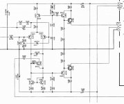
It's Yamaha amp. You can look at the full topology of Yamaha YST-SW800 at http://www.eserviceinfo.com/downloadsm/24380/yamaha_YST-SW800.html
Do you have a schematic? I'm not sure I'm visualising this correctlypeufeu said:As an emitter follower it's very stable (fixed collector voltage, CCS emitter load).
lumanauw said:It's Yamaha amp. You can look at the full topology of Yamaha YST-SW800 at http://www.eserviceinfo.com/downloadsm/24380/yamaha_YST-SW800.html
This may seem like a dumb question, but why would anybody bother to use a super pair in the design of a subwoofer amplifier?
Cheers,
Bob

I'm thinking of using it as the output follower in Hawksford's I/V, because the darlington in the original schematic gives me high distortion compared to an ideal buffer (in the simulator). I tried CFP which gives a good reduction in distortion, but someone on another forum said CFP sounds "closed" to him in whatever circuit he's seen it, and I tend to put some trust in his experience. So I was looking at other alternatives.
Does anyone know what the earliest occurrence of the Baxandall super-pair was? One presumes it was in something of Peter B.'s...
It, and several of its variants, do seem to be awfully useful, despite the stability margin issues. I'm also puzzled that it doesn't show up that I know of in integrated realizations---perhaps they are out there and since unpatentable, kept quietly proprietary. Certainly with dielectric isolation and good modern PNPs it would have utility.
Ah... with a little bit more searching this material showed up from audioasylum, posted by a jcox on 21 Feb 2002:
"
Baxendall, Constant-current source with unusually high internal resistance ..."
Electronics Letters , vol 2, 1966, p351
( I haven't read this article but it was referenced in:
"Active Filters for Integrated Circuits"
W.E.Heinlein and W. H. Holmes, 1974 )
Hawksford, Reduction of Transistor Slope Impedance Dependent
Distortion in Large-Signal Amplifiers
JAES Vol. 36, Number 4 pp. 213 (1988)
Largely forgotten during 70's, rediscovered/reinvented in 90's as
complementary bipolar IC processes and current feedback op amps
became popular
Hawksford's paper analyses circuit, shows near equivalence to
traditional cascode, shows many topological variants with
application to discrete audio amplifier design
( Hawksford may have been unaware of the Baxendall ref.)
Provides nearly 100x improvement in nonlinearity due to Hfe and
collector-base impedance variation over single transistor
( Ccb cancellation gives traditional cascode's speed as well )
NOT JUST A DARLINGTON!
"
bcarso said:
Ah... with a little bit more searching this material showed up from audioasylum, posted by a jcox...
that would be me before a computer seizure lost my cookies and password so I just shortened it to jcx
More papers re. the Baxandall/Swallow CS
Addl' reading that will be helpful to this topic:
"A high output resistance current source", Jaeger, R.C.;
Solid-State Circuits, IEEE Journal of
Volume 9, Issue 4, Aug 1974 Page(s):192 - 194
This is a ckt almost identical to Baxandall/Swallow (B/S). However, it does *not* reference them, but rather Tom Frederiksen:
"A Monolithic High-Power Series Voltage Regulator", Frederiksen, T. M.; Solid-State Circuits, IEEE Journal of
Volume 3, Issue 6, Dec 1968 Page(s):380-387
Within this voltage regulator is a discussion of a PNP output current source that functions similar to the NPN output B/S ckt (P384). It is attributed to Jim Thompson, a fellow designer with Frederiksen at Motorola during this period. From the timelines of the two bodies of work, it would appear that B/S and Thompson/Frederiksen independently developed similar configurations to minimize errors of the output device.
This type of current source became std within IC designs, as is documented by Alan Grebene, in his "Analog IC Circuit Design", Van Nostrand Reinhold, 1972, ISBN 0-442-22827-9.
If anyone has any additional references relevant to the Thompson/Frederiksen current source, please share them (thanks).
A second point which falls in this thread is the driven cascode, as termed "enhanced cascode" by Hawksford. This was seen prior to Hawksford's JAES paper, one example was within Erno Borbely's "High Power High Quality Amplifier Using MOSFETs", Wireless World, March 1983, Pages 69-75. Erno provides some pictures which show the reduction in distortion in curve tracer plots.
A similar type of driver stage to Erno's Fig. 7 was used in the Adcom series 565 and 585 power amplifiers. The distinction here is that for full effectiveness, the cascoding transistor base should be driven from the emitter of the bottom device, so that the collector and base see the same dynamic voltage, and consequently, greatest reduction in distortion.
Walt Jung
Thanks for that additional information Walt.
So (some) of it is in Grebene---alas my copy is in storage and who knows exactly where.
So (some) of it is in Grebene---alas my copy is in storage and who knows exactly where.
Re: More papers re. the Baxandall/Swallow CS
Hi Walt,
Thanks for these tidbits!
Good to see you here.
Cheers,
Bob
WaltJ said:Addl' reading that will be helpful to this topic:
"A high output resistance current source", Jaeger, R.C.;
Solid-State Circuits, IEEE Journal of
Volume 9, Issue 4, Aug 1974 Page(s):192 - 194
This is a ckt almost identical to Baxandall/Swallow (B/S). However, it does *not* reference them, but rather Tom Frederiksen:
"A Monolithic High-Power Series Voltage Regulator", Frederiksen, T. M.; Solid-State Circuits, IEEE Journal of
Volume 3, Issue 6, Dec 1968 Page(s):380-387
Within this voltage regulator is a discussion of a PNP output current source that functions similar to the NPN output B/S ckt (P384). It is attributed to Jim Thompson, a fellow designer with Frederiksen at Motorola during this period. From the timelines of the two bodies of work, it would appear that B/S and Thompson/Frederiksen independently developed similar configurations to minimize errors of the output device.
This type of current source became std within IC designs, as is documented by Alan Grebene, in his "Analog IC Circuit Design", Van Nostrand Reinhold, 1972, ISBN 0-442-22827-9.
If anyone has any additional references relevant to the Thompson/Frederiksen current source, please share them (thanks).
A second point which falls in this thread is the driven cascode, as termed "enhanced cascode" by Hawksford. This was seen prior to Hawksford's JAES paper, one example was within Erno Borbely's "High Power High Quality Amplifier Using MOSFETs", Wireless World, March 1983, Pages 69-75. Erno provides some pictures which show the reduction in distortion in curve tracer plots.
A similar type of driver stage to Erno's Fig. 7 was used in the Adcom series 565 and 585 power amplifiers. The distinction here is that for full effectiveness, the cascoding transistor base should be driven from the emitter of the bottom device, so that the collector and base see the same dynamic voltage, and consequently, greatest reduction in distortion.
Walt Jung
Hi Walt,
Thanks for these tidbits!
Good to see you here.
Cheers,
Bob
- Status
- Not open for further replies.
- Home
- Amplifiers
- Solid State
- Baxandall Super Pair