hi wendell c,
Looking good and thanks for posting. 😀
Resistors... Hugh always supplies good quality resistors in his kits, but I have used cheap ones on my BAKSA builds and haven't done a side by side test to determine how much difference they would make. I'd use what you have on hand and upgrade at a later date as you suggest.
The polystyrenes should work fine for Cdom. I'd start with the 68pF and work down. Hugh has already recommended to me that it should be lower than 68pF for Silver Mica. I have built amps with Silver Mica and amps with polystyrenes, but I have not swapped between them on the one amp to test which is better and if the values are different depending on type.
C4 is one cap that I have experimented with on my real AKSA, following advice from Rabbitz. It does make a subtle difference to the sound of the amp and is worth playing with.
I'll let Rabbitz or Hugh comment on the extra Silver Mica cap.😉
regards
The extra silver mica cap is from the real AKSA 55 so can't discuss it but IIRC it's the phase lead or something like that. Hugh has mentioned it in this thread but provided no details.
For C5 I used 47pF as that was the closest value silver mica I had on hand.
For C5 I used 47pF as that was the closest value silver mica I had on hand.
Hi, Greg.
I´m studying the Baby Aksa for a future build... where is the resistor R7? 😕
Regards.
I´m studying the Baby Aksa for a future build... where is the resistor R7? 😕
Regards.
Hi, Greg.
I´m studying the Baby Aksa for a future build... where is the resistor R7? 😕
Regards.
hi Sound_Buster,
I used the same component numbering on the BAKSA as the real AKSA. R7 exists on the real AKSA but it is one of the "missing" components on the BAKSA.
regards
Hi, Greg.
Ok. I realized it after other missings... I'm playing with the circuit in the Multisim, while not installed the LTSpice.
Regards.
Ok. I realized it after other missings... I'm playing with the circuit in the Multisim, while not installed the LTSpice.
Regards.
What changes are necessary for using it at lower voltage? (28V)
Does it work well with 3.5ohm speaker?
Does it work well with 3.5ohm speaker?
What changes are necessary for using it at lower voltage? (28V)
Does it work well with 3.5ohm speaker?
hi tpsorin,
Simple questions, hard to answer. 🙂
The amp will work with 28V voltages, but if you want to be scientific about it, the lower voltage will affect the current flow in the LTP and VAS stages so you should really recalculate the values of the LTP and VAS stage resistors to compensate.
If I remember correctly, the original AKSA 55 was not recommended for 3.5 ohm speakers, but my test speakers are 4 ohm speakers and I haven't had any issues. It really depends on what impedance your speakers dip down too and how hard and long do you intend to drive them.

Do you have teenage kids?

regards
My original AKSA 55 is used with speakers that dip down to 3R6 and it doesn't even blink at that load even at high SPLs.
IIRC I think the AKSA 55 was OK to 3R6 and the AKSA 100 was OK to 3R2.
My understanding is running lower rail voltages improves the low impedance drive capabilites but you lose some power.
IIRC I think the AKSA 55 was OK to 3R6 and the AKSA 100 was OK to 3R2.
My understanding is running lower rail voltages improves the low impedance drive capabilites but you lose some power.
I am glad to see you in action dear Rabbitz.
Some 4 ohms speakers can have very low impedances in some frequencies.
I could not measure that...but some guys told me that 2.5 ohms are not hard to find.
Do you think this is because the crossover Rabbitz?
Sound stage in the 55 is unbeatable!
regards,
Carlos
Some 4 ohms speakers can have very low impedances in some frequencies.
I could not measure that...but some guys told me that 2.5 ohms are not hard to find.
Do you think this is because the crossover Rabbitz?
Sound stage in the 55 is unbeatable!
regards,
Carlos
Last edited:
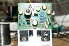
Some Vbe measurements
To help BAKSA builders with debugging, I have taken some Vbe measurements of the transistors of the first BAKSA I built.
Q1 (LTP) = 0.601v
Q2 (LTP) = 0.602v
Q3 (VAS) = 0.574v
Q4 (Vbias) = 0.616v
Q5 (Driver) = 0.589v
Q6 (Driver) = 0.579v
Q7 (Output) = 0.591v
Q8 (Output) = 0.582v
These readings look about what I would have expected. Please let me know if this is not the case.
Be careful not to short the leads of the transistors with the multimeter probes. I have heat-shrink on the exposed metal part of the probes except for the very tip.
hi Carlos
regards
This amplifier is interesting Greg...i see you're having progress on it
 Congratulations.
regards,
Carlos
Congratulations.regards,
Carlos
Some 4 ohms speakers can have very low impedances in some frequencies.
I could not measure that...but some guys told me that 2.5 ohms are not hard to find.
Do you think this is because the crossover Rabbitz?
Sound stage in the 55 is unbeatable!
regards,
Carlos
Hi Carlos
4 ohm speakers would be nominal only and in theory can dip to 2.8 ohm and still be called 4 ohm. Once you place drivers with a crossover then the raw driver impedance no longer applies and all bets are off. Some crossovers are more impedance friendly than others and AR series type crossovers tend to not have the roller coaster impedance curve that you find in some parallel crossovers.
It's important for the loudspeaker designer to take notice of the impedance curve as can have a detrimental effect on the power amp. I generally try and keep the impedance curve so dips and peaks sit within a 3 ohm range but that does not include woofer and port resonance peaks.
Thank you Rabbitz, i had some ideas about, but they were under suspitions only
Now, as i have your explanations, i am sure.
thank you,
regards,
Carlos
Now, as i have your explanations, i am sure.
thank you,
regards,
Carlos
Last edited:
OK, I need some help with debugging the BAKSA.
I have been in contact with Greg over the past week and he suggested I post on here to get a few more heads in the mix. With the info I have given we have not come to a fix.
Greg has given a few voltages from his build to compare.
The following is what I sent to Greg
q1/q2 0.7=1.05v
r4/c5 0.578=-33.5v
TP3/4 1.252=35v (i have suckout cap here)
TP1/2 .059=34.5v
OUT? .019=34.5
BIAS Vce 2.47= 0
I checked all voltage referenced to ground.
Also, I did some B-E voltage readings and all transisitors are 0.4-0.6v with the exception of q1 7v and VAS 2v.
I did remove q1 and VAS and tested with my transistor tester and came up fine, there were no shorts. So, I see no need to replace maybe problem is with something else.
Thanks
Attachments
post the actual Vbe of each transistor and the corresponding schematic so we can identify which is where........Also, I did some B-E voltage readings and all transistors are 0.4-0.6v with the exception of q1 7v and VAS 2v.
post the actual Vbe of each transistor and the corresponding schematic so we can identify which is where.
Hi AndrewT and Wendell,
Here's is the latest schematic with typical voltages (in red) measured from the first BAKSA I built.
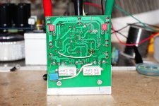
I have built 5 test amps using this PCB and BOM, (Rabbitz has built a couple, slightly modified) so we can assume that the PCB, schematic and BOM are OK. I have a feeling one or two of the transistors are swapped or reversed but can't tell from the picture.
It may be a solder joint but I understand Wendell has the same problem on both amps. Is the right Wendell?
Further information can be found here:
B-AKSA 55
regards
Attachments
Last edited:
Vbe
Q1 .633v
Q2 7.26v
Q3 2.61v
Q4 0
Q5 .448v
Q6 .448v
Q7 .503v
Q8 .504v
Hi Wendell,
Here's a guess. Here's the logic I used. Q1, Q5, Q6, Q7 and Q8 Vbe's are almost right, so I would assume they are OK. Q2 is probably OK because it is part of the LTP and Q1 is OK. Q3 VAS and Q4 Vbias values are bad, so one of these is causing the problem and they are both part of the middle section of the amp. Q4 looks OK in the picture assuming it is a BD139. So it must be Q3.
regards
If T2 has 7.26V across base/emitter, then it's damaged. Just why this happened is the question; excessive soldering heat maybe, incorrect alignment possibly.... Same is true for Q3; this is excessive and could also indicate damage.
Replace these devices, see what happens. LTP devices should be matched, however, so do T1 and T2 as a matched pair.
Replace these devices, see what happens. LTP devices should be matched, however, so do T1 and T2 as a matched pair.
Last edited:
- Home
- Amplifiers
- Solid State
- Based on Hugh Dean's AKSA 55