Hi all,
I just noticed what I think is a "minor" error in my schematic of the BAKSA. P1, the pot that's adjust Vbias, has the value of 1k on the schematics and BOM. Checking the original schematic (posted by Carlos many years ago) shows it should be 100ohm and a quick look at Hugh's original AKSA 55 schematic shows it is 100ohm as well.
I can't see any major problem though, other than the Vbias will be way, way under to start with, you will need to turn the pot many times before it gets close to the correct setting (roughly 60ohms), the sensitivity of the pot adjustment is effectively 10x greater.
If anyone can see a potential problem I would be grateful for the feedback.
regards
Ahhh that would probably explain why I had a lot of trouble finding the correct pot position in spice! I thought it weird that I had it in the high 90's for percentage of travel 😉
After doing nothing (on any of my projects) for the last 5 months, I'm starting to try and get organised, and thought if I'm ordering some parts for the others, I should check the bom for the BAKSA 🙂 Bit of a new years resolution to finish at the very least my active crossover/pre-amp, and hopefully once that is done build myself a BAKSA 🙂
Tony.
Member
Joined 2009
Paid Member
Looks like this has been a very successful thread !
The best place to hide something is out in the open 😉
I'm quite taken with the triple as an output structure and am going to revisit my TGM3 design to rebuild my home theatre amplifier. Eventually, I will build a SS follower with tube front end - I have all the parts but too many projects...
Even if I am a genius, the secret mechanism still eludes me.
The best place to hide something is out in the open 😉
Hmmm, this could be interesting. I'm sure Bigun is still planning on going "tubey" with this kind of approach too. Make it a triple SS output and get some real fireworks going!
I'm quite taken with the triple as an output structure and am going to revisit my TGM3 design to rebuild my home theatre amplifier. Eventually, I will build a SS follower with tube front end - I have all the parts but too many projects...
Nah, those transistor Vbe measurements look OK.
VAS is generally the lowest, followed by drivers, then outputs, then LTP.
What is not commonly realised is that Vbe varies considerably, on output devices up to about 1.5 volts when working hard. But 0.57-0.63 is a very good guide for checking idling circuits for DC faults.
Hugh
VAS is generally the lowest, followed by drivers, then outputs, then LTP.
What is not commonly realised is that Vbe varies considerably, on output devices up to about 1.5 volts when working hard. But 0.57-0.63 is a very good guide for checking idling circuits for DC faults.
Hugh
Just had a quick skim through this thread and I have to say, I may well build a couple of these to compare with my Symasyms. I have lots of the required transistors already from the bulk buy for those, so I'll just have to knock up a few PCBs. I suspect I do need to go through the thread in detail again to pick up on all the subtle hints that have been dropped! 🙂
Come on Jacco, you know me, it takes someone banging my head against a brick wall whilst screaming loudly for anything to register. You remember Pavel and the KrellKlone thread! 😀
I suspect I do need to go through the thread in detail again to pick up on all the subtle hints that have been dropped! 🙂
Yes... 😉 but don't forget:
B-AKSA 55
Best regards.
remember Pavel and the KK thread!
The good old days, dearly missed at times.
Smashing, thanks! 😀
The good old days, dearly missed at times.
Jacco, it's not like you to be maudlin! I know I've been away for a while, but there still seems to be plenty going on.
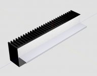
I've been playing with Eagle3D and POV to generate a nice 3D image of one of my BAKSA 55 test rigs. It's the first time I was able to generate a model with multiple boards and a Conrad heatsink (with flange). I plan to create a POV model of the case and include things like the power supply PCB and toriods etc.
It not a "real" advance with the project, but it has been interesting.
regards
It not a "real" advance with the project, but it has been interesting.
regards
Attachments
That heatsink mounting surface looks like it needs a trip through the fly mill though. 🙂
hi pinkmouse, 😀
I have a lot to learn about on applying textures on surfaces. On the Conrad flanged heatsinks only the top surface of the flange is machined. Originally I had the flange surface mirror finished but ended up with a reflection of blue sky and clouds which looked unusual. 🙂
The rest of the heatsink just has a cast finish.
regards
Attachments
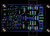
Soon to be tested
An externally hosted image should be here but it was not working when we last tested it.
Still lots more to do...😉
Hi pinkmouse,
I really like those off-board mounting holes.
There seems to be a problem with the spade pads but you probably already know that.
regards
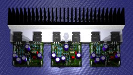
Hi Sound_Buster,
Nice build .
I have noticed some extra components, are they for DC offset adjustment?
What transistors have you used for the drivers and are they mounted face up or upside down? Just checking.
regards
Nice build .
I have noticed some extra components, are they for DC offset adjustment?
What transistors have you used for the drivers and are they mounted face up or upside down? Just checking.
regards
- Home
- Amplifiers
- Solid State
- Based on Hugh Dean's AKSA 55