Thanks for the reply. Resistance measures the same, bias voltages the same, anode voltages too. After swapping the tubes, with a proper meter, still have less on one channel than the other (tube swap not affected measurements, 35mA vs 75mA respectively). A bit confused, yet such a difference would really be audible.
Additionaly, measuring voltage drop accross the primary is similar on both channels, 14V, thats thats arround 59mA (primary DCr measured at 236Ohms
Hi Paulius,
Ale's schematic show the FIL+ connected to the 1,0Ω current sense resistor. This works for the older version of my filament regulator, but the RC-V9 (that you have) connects the negative side. Please check that FIL- is connected as the cathode in both cases.
Another check:
Please be sure that the Filament Raw DC in both channel is truly floating: disconnect the output and measure to chassis and to anode supply zero-volt return.
(DMM on 2kΩ range, or similar).
Film resistors canget unreliable if they get overloaded. If you have a spare, you can replace it.
Are you sure, that oscillation was not created in one channel?
It should be checked with oscilloscope.
Try to brake apart D3a VAS section and source follower (lift the coupling capacitor).
If measured difference is disappeared, the D3a may oscillating. As Ale wrote: ferrite beads on all pins.
I always use 100R carbon composite resistors instead of shorting (8, 9 pin to anode).
Be sure, that 1, 3 pins connected together.
That's a good point!Are you sure, that oscillation was not created in one channel?
It should be checked with oscilloscope.
You could remove the D3A as a quick check.
Ale sometimes mentions using ferrite beads in the driver tube pins. This can work in the grid, but it can make oscillation more likely, if applied to the cathode.
Hi,
Small correction, the driver is VT-25.. should I NOT be hearing this oscilation? I am Pretty sure regarding Rod’s comment on the floating supply and the resistor connected to the Negative regulator output, but will double check tonight
Small correction, the driver is VT-25.. should I NOT be hearing this oscilation? I am Pretty sure regarding Rod’s comment on the floating supply and the resistor connected to the Negative regulator output, but will double check tonight

Thanks on the input.
Performed checks and found a mistake - grounds of left and right fillament raw dc supply connected though a solid brass pcb post - fixed that with plastic spacers, and now can measure actual plate current, both tubes at 60mA. Would I benefit from running them any hotter? Anode voltage +390V, grid bias -80V.
Performed checks and found a mistake - grounds of left and right fillament raw dc supply connected though a solid brass pcb post - fixed that with plastic spacers, and now can measure actual plate current, both tubes at 60mA. Would I benefit from running them any hotter? Anode voltage +390V, grid bias -80V.
Attachments
Monolith SX-11 max. current is 120mA, but recommended working condition is 400V, 80mA.
KR300B is happy at 410V, 100mA, -80V operating point.
Try it at 80..100mA region.
If the voltage is lower (390V), lower bias voltage (-78 ... -75V) can produce about 80..100mA current.
Higher current always decrease THD, but higher primary current may increase lower bandwidth at high/er/ power.
For example datasheet shows saturation at 31Hz with 10W RMS.
Be sure, that HV power supply working well at high/er/ current too.
Yesterday tried some interesting things - +440V on the plate with -92 bias voltage, that resulted ~90mA of current per tube. This, combined with bypass of 1:4 step-up transformer ended up being almost religious experience - no electrical shocks - it just sounded VERY good. I was surprised that 3V line output from the DAC resulted still decent volume levels when feeding directly into VT-25.
Will try to enjoy this as much as possible, yet need to think about an upgrade path, perhaps somebody has suggestions? My knowledge is limiting the list to:
1) Component swaps - output transformers, coupling capacitors, driver and output tubes. 1:1 replacements to find what sounds best.
2) HV power supply - could be upgraded to properly handle 230mA and 450V, together with going back to tube rectification (now, because of the need for higher voltage, using 4x Schottky diodes.
3) LV power supplies - VT-25 heater raw dc supply is "only" CRCRC filtered, could experiment with choke loaded.
4) Is there a benefit of "opening up" the voltage gap for source follower like @euro21 wrote
Any other ides of improvement, part from putting everything in a chassis to be safe?
Thanks on the input!
Will try to enjoy this as much as possible, yet need to think about an upgrade path, perhaps somebody has suggestions? My knowledge is limiting the list to:
1) Component swaps - output transformers, coupling capacitors, driver and output tubes. 1:1 replacements to find what sounds best.
2) HV power supply - could be upgraded to properly handle 230mA and 450V, together with going back to tube rectification (now, because of the need for higher voltage, using 4x Schottky diodes.
3) LV power supplies - VT-25 heater raw dc supply is "only" CRCRC filtered, could experiment with choke loaded.
4) Is there a benefit of "opening up" the voltage gap for source follower like @euro21 wrote
For A2 capable 300B amp I usually use FET/SiC FET source followers CCS or resistor loaded to -220V, and much larger positive supply: +220 ...400V.
Any other ides of improvement, part from putting everything in a chassis to be safe?
Thanks on the input!
440V Ua and 90mA means 40W in the anode.
Running 40W with a standard 300B will mean a relatively short lifetime, and maybe not the best sound. Designs like the JJ, EH, or normal EML often sound better (IME) at 350-400V, especially if you don't have a big listening room.
but it does depend on the valve's manufacturer.
It's OK if you have an XLS or other super-300B, that are designed for higher voltage and power.
What type of DAC do you have? It needs good drive to handle a 1:4 IT + cable capacitance.
Hello Rod,
The 300B pair I am using now is KR 300B, which seem to be O.K. with higher power. I know this limits the lifetime, yet, if the sound is better, so be it. I will check the sound with 410/70-80mA again next time.
Tube datasheet:
https://www.tubeampdoctor.com/media/pdf/c3/05/b4/kr300b.pdf
The DAC hooked at the moment is Chord
Dave with 3V output. Sounds much better without the 1:4 IT (directly to the VT-25) and still atchieves reasonable volume levels with 94dB/W/m speakers.
@Rod Coleman thanks again for the support and the wonderful products that you are making. Never had a single problem thanks for the detailed instructions and support!
Well, I have got first more serious problem with the build: one channel source follower decided to short b- at the output - matter of fact - the input too. Perhaps somebody can help me out with this, so I don’t have to resolder the full board. What could be the causes and how can I avoid that in the future? There were no shorts, just a long swich off - on cycle when it did happen.
Other channel working perfectly happy with correct voltages.

Other channel working perfectly happy with correct voltages.
Measure T3 gate (left pin) to source (right pin). Failed FETs usually develop shorts here. Measure T1 the same.
If the short circuit is to B-, what resistance?
If T4 is shorted (C to E), I suspect oscillation.
If the short circuit is to B-, what resistance?
If T4 is shorted (C to E), I suspect oscillation.
@Rod Coleman thanks for the reply.
Had limited time (well, and knowledge) to troubleshoot, so just quickly esoldered the transistors on the board and its running fine again. Currenly at a more safer +400V on the anode and 80mA per tube, and using the CX301a line stage instead of 1:8 SUT and very pleased with the sound.
Had limited time (well, and knowledge) to troubleshoot, so just quickly esoldered the transistors on the board and its running fine again. Currenly at a more safer +400V on the anode and 80mA per tube, and using the CX301a line stage instead of 1:8 SUT and very pleased with the sound.
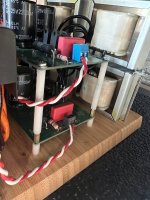
After 1.5 years of fiddling arround I can day that time has come to put this beast into a nice chasis. Perhaps anybody has hot ideas how I couls tweek the design and improve the sound? Output transformers are nano core monolyths, coupling caps are Vintate siemens Simatrops. Otherwise all remained unchanged.
My amplifier with 300b works perfectly with 420v/88mA, after 2 years the bias current has remained the same so I don't think there is a question of shortening the operating time and after several measurements of the various amplifiers made by me the most beautiful harmonic distributions are those located close to the anodic dissipation hyperbola
420v/88mA agree! PSU is a bit bordelline for that, so it would be wise to upgrade the 450V caps for a much higher voltage rating.
- Home
- Amplifiers
- Tubes / Valves
- Bartola 300B SE build