thank you jleaman.I get the photos.
to Anthony,your line converter unit looks very very smart 🙂Have you power on it and connect it to your sestem?YGPM😀
P.S.
the boards is still available.drop me a mail for orders.
regards
Zang
to Anthony,your line converter unit looks very very smart 🙂Have you power on it and connect it to your sestem?YGPM😀
P.S.
the boards is still available.drop me a mail for orders.
regards
Zang
Coulomb said:I finished a pair of boards and created a stand alone line converter with them that can be seen here.
What a nice box!
http://www.briangt.com/gallery/Balanced-Line-Drive/DSC00008
Where did you get it?
Carlos
carlmart said:
What a nice box!
http://www.briangt.com/gallery/Balanced-Line-Drive/DSC00008
Where did you get it?
Carlos
It is a stock Hammond Part. They come in all shapes and sizes.
The BLD is working great.
Regards
Anthony
That is an outstanding project. Very well done.
Where did you get that rectifier/cap/regulator board?
Where did you get that rectifier/cap/regulator board?
rabstg said:That is an outstanding project. Very well done.
Where did you get that rectifier/cap/regulator board?
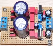
I had tried to fit Zangs regulator boards but they were to big. I ended up using a +/- power supply kit from a local hobby kit provider.
Regards
Anthony
Coulomb said:
I had tried to fit Zangs regulator boards but they were to big. I ended up using a +/- power supply kit from a local hobby kit provider.
Do you mean Walt Jung's regulators?
Even if I am great fan of them, I don't think there might too much of an audible difference in this case.
Carlos
carlmart said:
Do you mean Walt Jung's regulators?
Even if I am great fan of them, I don't think there might too much of an audible difference in this case.
Carlos
No, Zang (Digi01) put out some regulator boards,
Regards
Coulomb said:
No, Zang (Digi01) put out some regulator boards,
Oh, you mean the LM338 regulators to be used on the GC?
For the DVR134 you can use a smaller regulator, though my preference is with adjustable ones. Like the 3x7 or similar from LT. The LM 338 would be overkill here. They are also expensive and hard to find.
Carlos
Hi,
i agree, there's a nice plan of a 317/337 psu on nuuks' page: Preamp PSU @ NUUK
And this is it in nature, a little bit updated (protecting diodes, caps in parallel to the rectifiers, some small elkos around the regulator chips).
Michael
i agree, there's a nice plan of a 317/337 psu on nuuks' page: Preamp PSU @ NUUK
And this is it in nature, a little bit updated (protecting diodes, caps in parallel to the rectifiers, some small elkos around the regulator chips).
Michael
Attachments
slackman said:Hi,
i agree, there's a nice plan of a 317/337 psu on nuuks' page: Preamp PSU @ NUUK
And this is it in nature, a little bit updated (protecting diodes, caps in parallel to the rectifiers, some small elkos around the regulator chips).
Now that's a well made and compact supply for a prototype board! Great job!
It seems to follow Nuuk's reg layout, which is an excellent one.
Some tips for regulated PS that have been reported as improving audio quality:
1) Put a small cap, 1 to 10uF, in parallel with large adjusting resistor (P resistors in Nuuk's circuit). It improves noise.
2) Try a small cap, like 47uF, at the output and see if it improves noise.
3) Put a small resistor in parallel with output, like 1K or so, when you are feeding very low current chips. You can eliminate this if your current demand is constant and greater than 200mA. In any case watch the regulator's temp. Some regulators seem to be less noisy when facing a minimum constant current.
Don't forget the D resistors that you can see before the rectifiers.
If you want to go an extra mile, split the F capacitor in half it's value and put something like a 2~5 Ohm 5 watt resistors in series with +/- power lines.
Do not use resistors AFTER the regulators, as that will affect output's impedance.
Carlos
bridging gainclone with drv134
Hi.
I hope you allow a newbie like me ask some questions. I got a drv134 kit from Digi01. Very nice little kit. Digi01 has been very helpful in my trial for mounting this kit in order to bidge a LM3875 gainclone.
There is music coming through. But unfortunately there is some hiss too.This increases when I turn up the volume. And it does not seem to be more watt in this bridging amp than my other gainclone, eighter. May be I have mounted it wrong. But it may also be something else, that you might have experienced with drv134. Could you please give me some hints?
Thanks.
best wishes
jan ove
DRV134
The DRV134 is not actually a bridging adapter, but a ballanced line driver, and must be treated differently for a bridge configuration. The chip itself can impose as much as 20 to 30mv off DC offset, if there is DC offset at youre chips to start with and the referance points are not properly addressed you can have none linear gain causing Hissssss noise and un-ballanced operation.
First cap couple the input to the DRV134 use a 1K input resistor 22K to ground before the cap. The output should always have low value resistors 100 ohm minimum, canculate value by the number of chips and the input impeadance, 100 to 330 ohms is in range. This is important the sense leads should be coupled to the outputs with 10uf none poly film or simular high quality cap this prevents DC offset without effecting frequency response.
Re: DRV134
Sorry for not saying thanks for your advise. I have been very busy with my job duties lately and haven't have the time to check out replies.
You seems to be critical to use drv134 as a bridging adapter. After struggling for a while trying to get things to work, I tend to agree with you.
Searching in the whole DiYaudio community, now one seems to have succeded. Many mention the drv134, but no one seems to have completed a working amp. I tried Digi01's BLD pcb, but I got some loud "white noise" in addition. May be it is the grounding wire that is to long and picking up noise. May be it is me that has wired the whole thing wrong. But I'm ripe to try another solution 😡
I want to bridge two LM3875 so that it can be a bass guitar amp. The signal from the bassguitar goes in via a telejack connector and the output is also a telejack (6,3 mm). I prefer to have some gain, which the drv134 promised. But I'm willing to try other solutions.
Any suggestions, anyone?
best wishes
Jan Ove
tiltedhalo said:The DRV134 is not actually a bridging adapter, but a ballanced line driver, and must be treated differently for a bridge configuration. ...
Sorry for not saying thanks for your advise. I have been very busy with my job duties lately and haven't have the time to check out replies.
You seems to be critical to use drv134 as a bridging adapter. After struggling for a while trying to get things to work, I tend to agree with you.
Searching in the whole DiYaudio community, now one seems to have succeded. Many mention the drv134, but no one seems to have completed a working amp. I tried Digi01's BLD pcb, but I got some loud "white noise" in addition. May be it is the grounding wire that is to long and picking up noise. May be it is me that has wired the whole thing wrong. But I'm ripe to try another solution 😡
I want to bridge two LM3875 so that it can be a bass guitar amp. The signal from the bassguitar goes in via a telejack connector and the output is also a telejack (6,3 mm). I prefer to have some gain, which the drv134 promised. But I'm willing to try other solutions.
Any suggestions, anyone?
best wishes
Jan Ove
Balanced line driver - pcb kit
At last! Now the balanced line driver/drv134 pcb kit from Digi01 is repaired and working 🙂 I seem to have made some wrong soldering and connectings. But now it plays powerfully.
It still has some hiss, but this is to live with. This amp is going to be used as a bass amp. And on stage there will always be a lot of distortions anyway 😉
best wishes
jan ove
I use the AD SSM2142 😉
I will post my schematic later.
But I use a R100 Trimer to null the DC offset 😎
I will post my schematic later.
But I use a R100 Trimer to null the DC offset 😎
Balanced line driver - pcb kit
Please do! I'm very interested in how you trim the DC offset 😉
XELB said:I use the AD SSM2142 😉
I will post my schematic later.
But I use a R100 Trimer to null the DC offset 😎
Please do! I'm very interested in how you trim the DC offset 😉
Re: Balanced line driver - pcb kit
Hope this will help 😉
tangen said:
Please do! I'm very interested in how you trim the DC offset 😉
Hope this will help 😉
An externally hosted image should be here but it was not working when we last tested it.
Re: Re: Balanced line driver - pcb kit
XELB said:
Hope this will help 😉
Thanks a lot. I will certainly try this one.
jan ove
Where can I get the DRV134 (or DRV135) chips? I've scoured the internet, and I either have a minimum order for around 50 or more, or I have to wait 4 months for a sample from Texas Instruments.
- Home
- Amplifiers
- Chip Amps
- Balanced line driver, PCB layout share