boraomega said:Name is coming from names of our two countries: CROatia-SERbia....
And all that with a generous contribution (composite IGBT device idea) from our slovenian friend Andrej Lenart AKA Lazy Cat.

Big thanks to Andrej !

Does anybody remember if some of the Forte amps
were IGBT outputs? Which models and does anybody
have schematics?
were IGBT outputs? Which models and does anybody
have schematics?
juma said:
And all that with a generous contribution (composite IGBT device idea) from our slovenian friend Andrej Lenart AKA Lazy Cat.
Big thanks to Andrej !
I am ashamed... sorry Andrej!

No bad intentions, believe me!
Lazy Cat said:Thanks, Andrej Lakner 😀
Sorry Andrej, don't take it against me 😉
And to make sure we don't make this mistake twice, let's call this composite device of yours "Lakner's IGBT", ok? 🙂

I am encouraging people here to try to prototype my design in post #43 in this thread! That should work more than good!
Yes it is prototype, hence no 100% guarantee of success, but I generally rarely fail with designs, and I am quite confident it will work as predicted.
Yes it is prototype, hence no 100% guarantee of success, but I generally rarely fail with designs, and I am quite confident it will work as predicted.
I tried it p2p and it works although it sounded a bit muddy and grainy. DC offset was also a bit unstable.
Raising a current through JFETs and introducing a small amount of NFB (10-15 dB) solved these problems and then it sounded remarkably good.
After I get rid of my other amplifiers I'll be building this one properly - PCB and everything...
Excellent job, Bora & Andrej
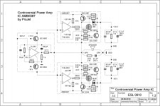
When I was finally satisfied with sound schematic looked like this:
Raising a current through JFETs and introducing a small amount of NFB (10-15 dB) solved these problems and then it sounded remarkably good.
After I get rid of my other amplifiers I'll be building this one properly - PCB and everything...
Excellent job, Bora & Andrej
When I was finally satisfied with sound schematic looked like this:
Attachments
Excelent Juma, but you "killed" the magic ... NonGlobalFeedback!
It shouldn't sound the way you describe (thou, it is quite possible that it may sound exactly like that now!). As it is still point2point, give it some more time and try to tweak it. Try to make currents through JFET-s equal as much as you can and to have about 10-12mA going through second simetr. cascode stage. Revert it back to my schematic (i.e. make it again NoGFB = remove R38), trimmer R1 put 100ohms, put R3=1k and R18=5k6. Those two values control the overall gain - gain is going up with lowering of R3 and/or rising R18. It might also need a capacitor about 470nF-1uF across C&E of your Q10.
Also, it might oscillate somewhere high in MHz spectrum (oscilloscope needed!) and then it will need two small caps of around 10-22pF between C of Q6 and B of Q5 and equally on lower side between C of Q7 and B of Q8. Grainy and muddy sound could easily be because of that!!!
Hi Boro!
Well, this is not the first no-GNFB amp I tried and all of them tend to sound more or less muddy when confronted with complex musical content. Certain amount of grain in sound is often the consequence of under-biased JFETs - IME j74/k170 sound best with bias of 70-90% of Idss when used in common source topology. Actually, the only novelty here is the Andrej's BIGBT output stage and it was the motive to give this amp a try.
The mods you are suggesting were first things to try but improvements are neglible.
Of course that I had to increase the open-loop gain in order to introduce GNFB and no sign of oscillations were detected with my scope (20 Mhz device).
The idea of an amp with no NFB loops is very appealing and gives a satisfaction to designer but when it comes to listening things are often not so swell anymore, unfortunately.
The amp is dismantled a month ago and right know I'm curious to find out how will BIGBT sound with Techno/Symasym VAS. The fun never stops, right? 😉
Boro, thank you once again for you numerous and valuable contributions to DIY community, it's people like you that make things happen.
All the best to you !
Juma, I saw the schematics and I have to say it has a potential to sound very good. I could understand that you've tried it with normal output stage already so you would have opportunity to compare two generic amps with different outputs. Nice. 🙂
Only that I'm worried about small amount of the second stage voltage gain.
Present GNFB lowers Zout of the amp and that if applied correctly should sound noncompromising even at demanding speakers. I could hardly wait to read about the results. I hope soon ...😀
Only that I'm worried about small amount of the second stage voltage gain.
Present GNFB lowers Zout of the amp and that if applied correctly should sound noncompromising even at demanding speakers. I could hardly wait to read about the results. I hope soon ...😀
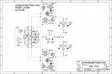
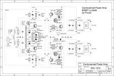
Controversial Power Amp
New schematics with BIGBT incorporated. Feel free to share, test, P2P ... 😉
New schematics with BIGBT incorporated. Feel free to share, test, P2P ... 😉
Attachments
Last edited:
IGBT Amplifier
I really like your idea Lazy Cat.
Seems what you have is here can easily be made into quite a good signal biased class A amplifier. For example, by adding collector resistors in series with the series cascode supply voltage regulator transistors supplying the TL061, the TL061 because of its very low quiescent current, will produce a voltage product by means of division through the series collector resistors, together with a current product in conjunction with the quiescent and dynamic current drawn by the TL061 through the series cascode supply voltage regulator transistors. Thus when a signal is applied to the TL061, the current across the collector resistors will become modulated proportional to a replica of the signal combined with the bias current.
You can translate that low quiescent current of the TL061 together with its dynamic current directly proportional to the input signal to establish and govern the bias current magnitude of the IGBT output stage driven by the THS 4631’s.
The THS 4631’s can then track and maintain each of the IGBT’s bias magnitude independently within its respective linear operating region relative to the dynamics of the load and functional characteristics of the IGBT. In another words, each THS 4631 drives the respective IGBT to develop (force) a match between the 0.22Ω sense resistor drop and the voltage and current command.
It also seems that one thing to look out for in this type of circuit is that the op amps utilized are maintained such that they are not able to latch up. In other words, the output may "latch" in the high (on) mode (saturate at full potential voltage). If the op amp receives an input signal supplied by a separate power source (an applicable example, a preamplifier) before its power supply has had time to reach total potential, the input voltage may easily exceed the power supply rail voltages.
In JFET-input operational amplifiers, latch-up may occur if the input voltage approaches too closely (within 0.7 volts) to the negative power supply rail voltage.
Even if the op-amp in question is per its manufacturer “protected” against latch-up, at the very least, the op-amp's behavior may become quite unpredictable. At worst, the latch-up may be destructive to the op-amp and additionally to interrelated circuits like the IGBT’s, or speaker. Perhaps a sequenced power up may be needed.
Another issue may prove to be high frequency oscillation (in the MHz range). Some clever frequency limiting may need to be applied.
Like I said though, I like your idea and it is very worth experimenting with. The same idea could be applied with Mosfets too.
Rich B.
Controversial Power Amp
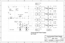
Improved version of the Controversial Power Amp with super-stabilised DC operating conditions. Features separate BIAS regulation for both output BIGBT devices and a very basic-simple DC-servo regulation based on inverting character of the main current sources. 😉
Improved version of the Controversial Power Amp with super-stabilised DC operating conditions. Features separate BIAS regulation for both output BIGBT devices and a very basic-simple DC-servo regulation based on inverting character of the main current sources. 😉
Attachments
![AccelEDA - [Sheet1].JPG](/community/data/attachments/191/191158-2eb72d6f201c78b3aefdfea2e222bfdc.jpg?hash=LrctbyAceL)
![AccelEDA - [Sheet1].JPG](/community/data/attachments/169/169644-882dc888dd7bb71de66bbb1cbffb99ea.jpg?hash=iC3IiN17tx)

- Status
- Not open for further replies.
- Home
- Amplifiers
- Solid State
- Balanced IGBT for amplifier output