Boy, after all that's been going on here, I really would have thought papa would be offering more wisdom and stuff... Maybe that's a sign we're doing good?
I mean, I'm spilling my worthless gut's trying to figure this out and he didn't think I needed any correction?
Melon Head 😛 Can't help it... I honsetly couldn't see that stuff with out saving and reopening but the txt sounded good. (it's Friday night!) Now it's to late for me to keep going to much. The last couple were rediculously dense and unseeable. You only need a few mS of 1kHz not 20 cycles?
Actually, the people who send the confused souls to N.P.s articles are right, they should go there first! You did find a good way to do this without all them difficdult concisely accurate words I have to think up.
reading without understanding...well, I do that all the time
in a hope that I will understand it better next time
but its still important to remember them words
they could the key that ties it all together
in a hope that I will understand it better next time
but its still important to remember them words
they could the key that ties it all together
I think it's important to remember that this is actually
simple stuff. There is no big trick. Once you get it, you'll
smack yourself on the forehead.
😎
Once the understanding is evident, and the desire for cheese (to accompany the winning) is satisfied, I'll slap myself 😎
i havent read through all of this yet, but i can say for me, i am very thankful to everyone who has contributed to what looks to becoming quite a nice little resource  and dont worry flg, to me from what i have read you are making perfect sense and the format is fairly easily digestible. that goes for all of you, thankyou for taking the time
and dont worry flg, to me from what i have read you are making perfect sense and the format is fairly easily digestible. that goes for all of you, thankyou for taking the time
Last edited:
So we still get 2 x 1.3A Class A of a stock F5, but the two halves are in series (I think series is the right word) with the load so we don't get 5.2A class A from our 2.6A bias.
I hope that makes sense
I hope that makes sense
Last edited:
I hope these posts help to explain things rather than add more confusion.
http://www.diyaudio.com/forums/pass-labs/172770-balanced-f5-question-15.html#post2414954
http://www.diyaudio.com/forums/pass-labs/121228-f5-power-amplifier-176.html#post2282360
http://www.diyaudio.com/forums/pass-labs/121228-f5-power-amplifier-39.html#post1639404
If the latter then I better leave Nelson to explain in simple terms.
He can do that much better than I, and he has a lot more patience, if not also more time.
😉
Patrick
the two halves are in series (I think series is the right word) with the load so we don't get 5.2A class A from our 2.6A bias.
Appologies. I think that statement is bollocks.
My guess about the reason why you don't get 5.2A max Class A in the F5X is because the signal running through each pair is 180 degrees out of phase so you don't get summing of 2.6A + 2.6A max class A of each half.
A stock F5 with 2 parralleled pairs each biased at 1.3A (2.6A total bias) gives you max class A of 5.2A because the signal coming from each pair is completely in phase so you get 2.6A + 2.6A from each pair, which is obviously 5.2A.
Well this might be bollocks too. But it is my best dumb guess.
Nelson, you would be surprised how much basic stuff we don't know. If this is wrong Nelson please put me out of my misery.
Last edited:
Here is more additional guessing. Some serious guess work going on here. If I get this right I might be kicked out of the dumb club.
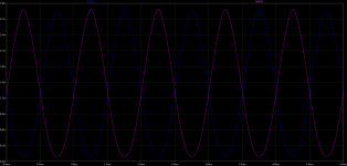
At the middle of the load we have a virtual earth.
When we have +10V coming from one half of the amp we also have -10V coming from the other half of the amp.
+10V referenced to -10V is 20V. However when we have our max +2.6A coming from one half of the amp we have 0A coming from the other half of the amp.
2.6A referenced to 0A is 2.6A. So we don't get 5.2 A.
Last edited:
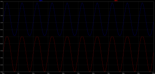
I think this proves my guess (I am too dumb for theories).
When IdM1 is at max current IdM7 is at basically 0 current, and vice versa.
If I got this right, I just reinvented the wheel or reinvented 1st year University Text books across the planet
When IdM1 is at max current IdM7 is at basically 0 current, and vice versa.
If I got this right, I just reinvented the wheel or reinvented 1st year University Text books across the planet
Attachments
Last edited:
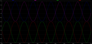
And here is the complete picture.
When IdM1 is at max positive current IdM7 is at 0 current and vice versa.
When IdM2 is at max negative current IdM8 is at 0 current and vice versa.
Nelson if this is wrong then please say so. I don't care actually. If I am wrong then it is more evidence to say that I am dumber than Zen Mod (I am trying to build up a strong case)😀
Attachments
no way Jose ;
it's well known who's dumbest around
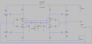
you even know how to power up that sim .........
tip - just look what's current through load - then it's easy to see where it's coming from .
another tip - decrease load resistance and push those buggers in clipping - it will tell you even more
edit : maybe you can post zipped asc file ..... so somebody else can play with , too ......
it's well known who's dumbest around
you even know how to power up that sim .........
tip - just look what's current through load - then it's easy to see where it's coming from .
another tip - decrease load resistance and push those buggers in clipping - it will tell you even more
edit : maybe you can post zipped asc file ..... so somebody else can play with , too ......
another tip - decrease load resistance and push those buggers in clipping - it will tell you even more
I already did that. I don't have a problem with that part of the operation.
Just trying to explain for the benefit of all why you don't get 5.2A max class A from F5X biased at 1.3A + 1.3A.
I think I have explained it correctly however if I am wrong, I will be making a claim for the title of King Dumb😀
Since this is the balanced thread, I shall only comment on the balanced version.
The definition of Class A is that one transistor goes to near switch-off. So for a balanced circuit biased at 4A in total, the top left MOSFET (say) goes to 0A, and the top right MOSFET goes to 4A; the bottom right to 0A, and the bottom left to 4A. A net positive current of 4A now flows from the positive power supply rail through the top right FET (as only the top right FET is on, and the bottom off) to your speaker, returns to the left side where it is drained to the negative rail via the bottom left FET.
i.e., the maximum Class A current output equals the total DC bias in a balanced circuit, and the power supply sees a constant current consumption (over-simplified as total device linearity is assumed, which is not reality).
As Nelson said, very simple. 😉
Patrick
.
Last edited:
All, good review of the basics of Class A and power consumption in these series of entires.
Just remember--if all else fails, just repeat the Melon Head mantra to yourself, about a dozen times:
"An amp so simple, even a came man could build it".... 🙂
Just remember--if all else fails, just repeat the Melon Head mantra to yourself, about a dozen times:
"An amp so simple, even a came man could build it".... 🙂
Melon Head,
In a balanced amp, the output currents are Xed.
From the top of an amp to the bottom of the otherone.
And reciprocal.
When one branch of the X reaches 2.6A the other one reaches 0A.
Which is the definition of leaving classA.
And yes, it's a serial crossed connection.
In a balanced amp, the output currents are Xed.
From the top of an amp to the bottom of the otherone.
And reciprocal.
When one branch of the X reaches 2.6A the other one reaches 0A.
Which is the definition of leaving classA.
And yes, it's a serial crossed connection.
Last edited:
Since this is the balanced thread, I shall only comment on the balanced version.
The definition of Class A is that one transistor goes to near switch-off. So for a balanced circuit biased at 4A in total, the top left MOSFET (say) goes to 0A, and the top right MOSFET goes to 4A; the bottom right to 0A, and the bottom left to 4A. A net positive current of 4A now flows from the positive power supply rail through the top right FET (as only the top right FET is on, and the bottom off) to your speaker, returns to the left side where it is drained to the negative rail via the bottom left FET.
i.e., the maximum Class A current output equals the total DC bias in a balanced circuit, and the power supply sees a constant current consumption (over-simplified as total device linearity is assumed, which is not reality).
As Nelson said, very simple. 😉
Patrick
.
Thanks Patrick. Which I think agrees with what I discussed earlier below and backed up with simulated results
My guess about the reason why you don't get 5.2A max Class A in the F5X is because the signal running through each pair is 180 degrees out of phase so you don't get summing of 2.6A + 2.6A max class A of each half.
when we have our max +2.6A coming from one half of the amp we have 0A coming from the other half of the amp.
I think this proves my guess (I am too dumb for theories).
When IdM1 is at max current IdM7 is at basically 0 current, and vice versa.
And here is the complete picture.
When IdM1 is at max positive current IdM7 is at 0 current and vice versa.
When IdM2 is at max negative current IdM8 is at 0 current and vice versa.
Last edited:
- Status
- Not open for further replies.
- Home
- Amplifiers
- Pass Labs
- Balanced F5 question