Thank you thanh. I was just getting a little sick of the behaviour and comments from some people here 😕 Respect for science and respect for all the fellow forum members along with respect for the hobby is not the same. I'm struggling to maintain myself right now...
I would like to apologise to those Tee'ed off by me going off on Patrick... I thought maybe he needed it?
...
I am sure we have all felt like this at one time or another on the forum. If you hang out here long enough, I think you begin to mellow quite a bit and start to value people even the annoying ones. I know I have.😎
Anyway it is good to see everyone has calmed down, and we can move forward. There quite a few ways we can skin this cat, it might take some time, but we will get there.
Here is one of my favourite movie quotes:
"Dad reckons fishing is 10% brains and 95% muscle, the rest is just good luck" The Castle
I love the math there. I wonder what percentage is good luck.
If you can get hold of this movie, I highly recommend it. It is an Australian movie, so I am not sure if the humour has international appeal, but I rate it as an all time classic.
Last edited:
Hi Thanh
I realy apreciate the work you are doing and was wondering what may happens if you use a cooper bar as heat spreader maybe a scrap piece of buss bar?
On another note and probably not my place to post this but as we got carried away.
The PCB is now on the verification stages.
Is down to Patrick to decide when to move this forward.
And as I think I am getting to know him it only will be once perfect.
Which I think is worth waiting for.
Kindly do not harass him at this stage and be patient.
Al
Renewed request for assistance :
I need one more volunteer with experience in PCB layout to double check my ACAD drawings vs those from bksabath.
Please send me a PM if you have a dwg viewer, and are willing to do the donkey work.
Thx,
Patrick
I need one more volunteer with experience in PCB layout to double check my ACAD drawings vs those from bksabath.
Please send me a PM if you have a dwg viewer, and are willing to do the donkey work.
Thx,
Patrick
Kind of quiet, so I should perhaps provide some excitement.
Since I heard no response for cross check volunteers, and I cannot spot any obvious mistake, I have asked Sandro to generate the Gerber files.
Once we have checked those as well, I shall send them to Variac.
Then my task is finished as promised, and the rest is up to him (when, how much, what format, ....)
So PCB almost done.
Patrick
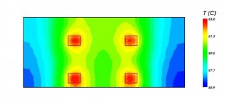
I did some thermal simulation today to see how far we can optimise the heat source positions.
This is the first (well optimised) result.
You should not look at the absolute values, as I used 25°C ambient.
The exercise is aimed at minimise temperature variations over the heat sink area.
So you should look at the difference between max and min, and compared those to thanh's experiment.
As you can see, by clever heat source placement, you can get the temperature difference down from dT = 20°C to dT = 7°C.
(The relative positions of the MOSFETS are as per F5X PCB.)
Patrick
Attachments
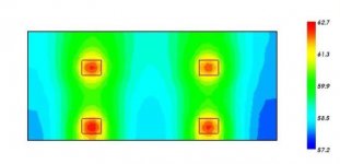
What if we put the MOSFETs wider apart across the width, say by another 40mm ?
As you can see, only very slight improvement, especially to Tmax. So we are already very near to the optimum.
As I already mentioned, the geometry of the fins is such that increasing height to 200mm brings very little improvement, but jacks up costs by some 30%.
So if you want to dissipate more, you need a wider sink, which makes heat spreading with 4 MOSFETs even more of a compromise (to the PCB layout).
Patrick
Attachments
Last edited:
So if you want to dissipate more, you need a wider sink, which makes heat spreading with 4 MOSFETs even more of a compromise (to the PCB layout).
Patrick
How does spreading the MOSFETS make it more of a compromise?
Just out of curiosity, how long you waited for temperature to stabilize over the heatsink? I was just doing a test on some heatsinks I have, and I was observing temp. changes over the time. It was surprising, to me, that it really takes a long time for temperature to spread around the whole heatsink and to sort of stabilize. Great thermal shots!
Normally 1 to 1.5 hours, if the room temperature does not move.
But then I have large sinks (large thermal masses) on my towers.
Patrick
But then I have large sinks (large thermal masses) on my towers.
Patrick
Thankyou EUVL!
I very much appreciate your efforts. I would be glad to do the task, but do not have the requisite knowledge. I can not wait for the boards to be ready, but I will have to!
Much appreciated!
Russellc
I very much appreciate your efforts. I would be glad to do the task, but do not have the requisite knowledge. I can not wait for the boards to be ready, but I will have to!
Much appreciated!
Russellc
So how thick does a copper heatspreader need to be in order to be effective? [/thinking out loud]
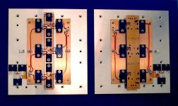
I show you one example of the use of heat spreader -- my 7 year-old AXJ100 design.
There are two levels of heat spreaders -- a 12mm thick aluminium plate 230x200mm, and copper busbars 4mm thick x 40mm wide. 0.5mm Aluminium oxide insulators between aluminium and copper with aavid Ultrastick both sides. The MOSFETs are thermally and electrically coupled to the copper by conductive silver grease.
You can think about the cost and whether this is what you want to do.
This will not be the default solution I offer for the F5X.
Patrick
Attachments
Last edited:
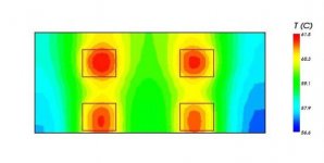
Someone asked by PM what if we solder the MOSFET to a larger piece of copper.
While I cannot entertain all wishes for endless simulations, which cost both time and money, I will do this one particular one, just to end the discussion.
You can see that under same conditions except for a larger heat source size (50x40mm), and renew optimised heat source postions but maintaining the F5X layout, the gain on Tmax is an entire 1.5°C.
40 Bucks for 1.5°C can only be good for psychology, does nothing to improvement MOSFET lifetime, which does not need any improvement in the first place, IMHO.
Patrick
Attachments
cool pics Patrick!! i'll go the copper bars, but only because they are fairly easily available and look cool too 😱
You can always device your own customised solution, like rhodium plated solid silver busbars.
I am sure they probably sound better too ........
😉
Patrick
I am sure they probably sound better too ........
😉
Patrick
haha, what you mean it could sound better?? well then..... how long should I burn them in before passing judgement? should I run the temp right up for this? I dont think i'll go with the rhodium because it might be to bright combined with my silver fuses
nah but seriously, I was just going to line the sinks with 2 x 2mm thick sheets and bond with Ag epoxy. I was thinking just 1 x 2mm sheet, but your post above got me thinking that wouldnt be enough. over 2mm and its a custom solution from my usual supplier, so either 2 x 2mm, or i'll contact another company down in melbourne. I need to get some for other builds anyway so its a matter of adding to the order and I am a sucker for copper
nah but seriously, I was just going to line the sinks with 2 x 2mm thick sheets and bond with Ag epoxy. I was thinking just 1 x 2mm sheet, but your post above got me thinking that wouldnt be enough. over 2mm and its a custom solution from my usual supplier, so either 2 x 2mm, or i'll contact another company down in melbourne. I need to get some for other builds anyway so its a matter of adding to the order and I am a sucker for copper
Last edited:
You can think about the cost and whether this is what you want to do.
This will not be the default solution I offer for the F5X.
Patrick
I understand that it won't be the default solution offered, I'm just merely mulling over the options and possibilities 🙂 Thanks Patrick!
-Ben
In a thermal chain where the ambient temperature is 22°C, and the junction temperature is 100°C, how much money is it worth spending to lower than by say 3°C in the most optimistic case ?
If your argument is that you like polished copper shining from your housing, then it is another story. Then it can be worth 20,00 bucks.
And we shall be most happy to supply you with a housing with a see-through top, at a bargain price which is only a fraction of the 20 grand !!
😉
Patrick
If your argument is that you like polished copper shining from your housing, then it is another story. Then it can be worth 20,00 bucks.
And we shall be most happy to supply you with a housing with a see-through top, at a bargain price which is only a fraction of the 20 grand !!
😉
Patrick
Last edited:
- Status
- Not open for further replies.
- Home
- Amplifiers
- Pass Labs
- Balanced F5 question