Well, I'm using "Zen" in the single-stage sense. I don't think the original '94 Zen is an example of Schade feedback.
I Know htis sounds lazy to just ask this, without doing my own research but… Could i just drop the volts and current to build a 25w version? Any ideas on volt and current spec.to get me in the ball park? thank you anyways
I Know htis sounds lazy to just ask this, without doing my own research but… Could i just drop the volts and current to build a 25w version? Any ideas on volt and current spec.to get me in the ball park? thank you anyways
Just use standard transformer with 2x18V secondaries connected in series to give you between 44 and 46V dc single ended power supply.
I'd still maintain the 3A or 3.2A bias arrangement.
Hello Mr. Chul - good going! I already have Jensen 1:1's but also plan to use my LDR-driven passive. Picture shows it with my passive speaker EQ.
Would you mind measuring the ripple voltage of your 48V SMPS alone then together with the Boost DC/DC converter in the chain so we can see the effect of the DC/DC converter, if there is any? Thank you.
Just call me Chul, part of my first name 😉
I know the LDR sound! Yours seems to be alble to adjust the maximum value. Which is good.
I will get that AC ripple voltage this morning. I have this 10 ohm 100Watt WW resistor for a load, since ripple may change with actual current?
Nelson wrote that 0.5ohm between two 47000UF would make a good supply, and I think this CCS remove some of the ripple better than resistor or choke load.
Just did this
Hi ci11,
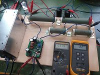
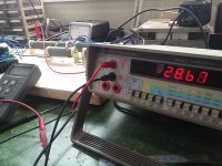
Please see the pictures. I used total 18 ohm load resistors(10+4+4). In short with 48VDC from SMPS and 60VDC from converter, I have 32mV from SMPS and 24mV from converter. I added 47000UF capacitor and this made it to 22mV. 🙁
This may be OK for me, since I use a very low efficiency speaker. But with Lowther or other full range we need quieter supply?
I had fun burining the WW resistors, these are at their maximum rating. 😀
Chul
Hi ci11,
Please see the pictures. I used total 18 ohm load resistors(10+4+4). In short with 48VDC from SMPS and 60VDC from converter, I have 32mV from SMPS and 24mV from converter. I added 47000UF capacitor and this made it to 22mV. 🙁
This may be OK for me, since I use a very low efficiency speaker. But with Lowther or other full range we need quieter supply?
I had fun burining the WW resistors, these are at their maximum rating. 😀
Chul
Attachments

{snip} I don't think the original '94 Zen is an example of Schade feedback.
looks pretty Schade-y to me 😀
Attachments


Hi ci11,
Please see the pictures. I used total 18 ohm load resistors(10+4+4). In short with 48VDC from SMPS and 60VDC from converter, I have 32mV from SMPS and 24mV from converter. I added 47000UF capacitor and this made it to 22mV. 🙁
This may be OK for me, since I use a very low efficiency speaker. But with Lowther or other full range we need quieter supply?
I had fun burining the WW resistors, these are at their maximum rating. 😀
Chul
Don't forget the amp has a decent amount of PSRR.
Hi ci11,
Please see the pictures. I used total 18 ohm load resistors(10+4+4). In short with 48VDC from SMPS and 60VDC from converter, I have 32mV from SMPS and 24mV from converter. I added 47000UF capacitor and this made it to 22mV. 🙁
This may be OK for me, since I use a very low efficiency speaker. But with Lowther or other full range we need quieter supply?
I had fun burining the WW resistors, these are at their maximum rating. 😀
Chul
Hi Chul,
Thanks for running the tests and the pictures. Looks like neither the SMPS and the boost DC/DC converter can cut it for this circuit.
When papa replied with the 0R5 between 2 47K caps, he also mentioned that both the R and C values can be changed. In my own back-of-the-napkin math, it was looking more like at least 272K and a 1R5 to get to around 2mV. I would be happier at this level since my speakers are 4 Ohm dipping occasionally to 2.
So thank you once again and it looks like more work ahead!
Don't forget the amp has a decent amount of PSRR.
Yes, and that CCS makes me feel a little more comfortable about ripple. 🙂
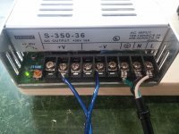
I tried more common type 36V 10A SMPS frm ebay, and I get 32mV. I am keeping them connected as it is for some hours.
I hope the PCB is being cooked by somewhere.🙄
Chul
Attachments
looks pretty Schade-y to me 😀
I must not understand how we're defining "Schade" feedback. Perhaps you can help me there.
Hi Chul,
Thanks for running the tests and the pictures. Looks like neither the SMPS and the boost DC/DC converter can cut it for this circuit.
When papa replied with the 0R5 between 2 47K caps, he also mentioned that both the R and C values can be changed. In my own back-of-the-napkin math, it was looking more like at least 272K and a 1R5 to get to around 2mV. I would be happier at this level since my speakers are 4 Ohm dipping occasionally to 2.
So thank you once again and it looks like more work ahead!
Hi ci11,
One more thing, we have all these "stones to throw at the walll" 😀
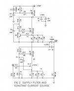
I just tried the FET supply filter and it seems to work. A little more voltage for the FET (about 4V? this is OK with this converter) and a little more heat (I am OK 🙂 ) ... We have 2mV now.
Of course I would go for simple linear CRC supply with right formula, but this is also fun to play.
Cheers
Attachments

Last edited:
Just use standard transformer with 2x18V secondaries connected in series to give you between 44 and 46V dc single ended power supply.
I'd still maintain the 3A or 3.2A bias arrangement.
This is what I will be/am doing. Have the transformers and the TeaBag PSU boards with 63V caps. 😀
Hi ci11,
One more thing, we have all these "stones to throw at the walll" 😀
I just tried the FET supply filter and it seems to work. A little more voltage for the FET (about 4V? this is OK with this converter) and a little more heat (I am OK 🙂 ) ... We have 2mV now.
Of course I would go for simple linear CRC supply with right formula, this is also fun to play.
Cheers
Hi Chul,
Way to go! What an ingenious find. Congratulations! So what do I do with the 16x 68K caps that are on their way here???
On another note, I had originally planned to build the CSX Part 2. Other than the VFET's most other parts are already on hand. Then BAF and this beast and it's a whole new ball game. The idea for PSU on the CSX Part 2 was going to be like papa's original BAF VFET with the outboard PSUs as shown in his CSX Pt 1 article. My PSUs are 2 32V 10A single channel units for the VFET's and a 15V 5A dual channel unit for bias. Each of each PSUs measure at <1mV ripple. It should sound pretty decent.
However, they have fans and that kinda spoills the party so I decided to go with a linear supply driven by a Variac and an isolation transformer, running AC lines to the 2 monoblocks where it is rectified next to the 272K caps. So if your SMPS layout keeps getting better, it would be going back to square 1 for me again....
So thank you, really!
I must not understand how we're defining "Schade" feedback. Perhaps you can help me there.
Hi Mike,
I remember the same feedback from tube circuits, called partial feedback. The claim is the same, that it makes pentode work like a triode. I really liked this feedback with tubes. I do not know which name is the right one but I do not mind. 😀
Check the resisotor between plate and grid of the output tube. This resistor is also used as a load resistor for driver tube. There is a blog on this on More Hybrid-Amplifier Design
Chul
Attachments
Way to go! What an ingenious find. Congratulations! So what do I do with the 16x 68K caps that are on their way here???
Please don't count on this.😱 Our ears will be the judge anyway. I just tested the cicuits by Papa. You can keep those caps in the drawer like he does for future project.. 🙂
I am so hooked on this SIT single ended magic.. now with Mike's Luminaria SIT pre the sound is like never before. I just want more power for my speaker.
Chul
I must not understand how we're defining "Schade" feedback. Perhaps you can help me there.
This thread has some useful background including the spice sim that nelson showed at the BAF:
http://www.diyaudio.com/forums/pass-labs/281233-schade-circuit-using-irfp240s.html
Also, I think i mentioned it earlier but in case I didn't: Thank you Mike, so very much for giving us the videos of BAF !!

yup , that goes long way back ........
O. H. Schade …… Beam Power Tubes , article about special feedback , 1938 | Zen Mod Blog
O. H. Schade …… Beam Power Tubes , article about special feedback , 1938 | Zen Mod Blog
we also note that the transformer input Ixys hockey puck amp is the innovation which makes it distinct to traditional Schade....
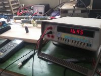
I was wrong..
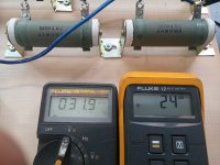
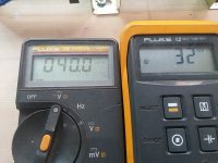
I've been watching the ripple and found that the readout is unstable. I tried other multimeter that I have and it seems that the ripple is not good..
29mV. after the converter with FET filter
17mV after the converter with FET filter + 47000UF
Hey ci11 I am sorry for the hasty posting. At least you can use those caps.
Chul
Attachments
Last edited:
- Status
- Not open for further replies.
- Home
- Amplifiers
- Pass Labs
- BAF 2015 Coverage