Just one more dumb thought.
In it's most pure form of Schade feedback you are putting a very linear device ie resistor in parallel between gate and drain, in addition to feedback effect would this also help linearise the device (sought of like degeneration effect with source resistors)
The brain doesn't know what to think about that.
Please don't confuse what I am saying with Bob Cordell's ideas (they are way over my head).what you're intending is to make distinction between "usual" NFB and error correction ...
When I say correction I just mean feedback, feedback is a form of correction. Sorry for using those terms. I'm not a fan of Cordell Error Correction.
I didn't mention Cordell , error correction as term/physical process existed long before him ..... and I'm using it here in most crude/basic meaning - assuming junction where (part of) output signal is compared/summed with pure input signal
inverting OP arrangement as example , vs. non-inverting OP NFB arrangement , where NFB summing junction is not containing pure/non altered input signal
so , most probably exactly what you meant
inverting OP arrangement as example , vs. non-inverting OP NFB arrangement , where NFB summing junction is not containing pure/non altered input signal
so , most probably exactly what you meant
Regarding heatsinking I found this one while looking around:
Heatsinks: 9000 Series - 9800HS | BAL Group Ltd
300mm length with a 120mm fan at low speed should give 0.03C/W, more than enough for 200W dissipation!
I'm not sure of the natural convection numbers though...
Heatsinks: 9000 Series - 9800HS | BAL Group Ltd
300mm length with a 120mm fan at low speed should give 0.03C/W, more than enough for 200W dissipation!
I'm not sure of the natural convection numbers though...
...I'm not sure of the natural convection numbers though...
I think the numbers are on the chart below the specs, just point the cursor to the blue line and the actual number shows up in a box. It looks like it will need the fan for sure.
I didn't mention Cordell , error correction as term/physical process existed long before him ..... and I'm using it here in most crude/basic meaning - assuming junction where (part of) output signal is compared/summed with pure input signal
inverting OP arrangement as example , vs. non-inverting OP NFB arrangement , where NFB summing junction is not containing pure/non altered input signal
so , most probably exactly what you meant
Yeah looks like you understood exactly what I was trying to say.
I often describe this stuff in my own words. I was starting to worry that my use of terminology could possibly add confusion so wanted to make sure we understood one another
What could be the better bias solution for this 4.7V? What I can think is an independent transformer circut using bridge-cap-positive regulator-cap and adjusting pot, or can I just have the voltage divider from the supply or at the 28V point?
Thank you for your tip in advance.. 🙂
Thank you for your tip in advance.. 🙂
What could be the better bias solution for this 4.7V? What I can think is an independent transformer circut using bridge-cap-positive regulator-cap and adjusting pot, or can I just have the voltage divider from the supply or at the 28V point?
Thank you for your tip in advance.. 🙂
The voltage reference needs to be absolutely rock solid for this device.
nothing wrong with LM324 , lately popular in FW stable
Pa probably bought few containers of them

Pa probably bought few containers of them
What could be the better bias solution for this 4.7V? What I can think is an independent transformer circut using bridge-cap-positive regulator-cap and adjusting pot, or can I just have the voltage divider from the supply or at the 28V point?
Thank you for your tip in advance.. 🙂
nothing wrong with LM324 , lately popular in FW stable
Pa probably bought few containers of them
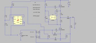
Don't know if Nelson has been waiting for us to get off our fat lazy *****, but here is what my brain can put together. It works completely fine.
R12 is a trim pot. It might be best to convert R12 into 10k resistor + 25 Turn 10k trim pot. You need very fine adjustment.
Hopefully you bastards appreciate this.
Attachments
Last edited:
trivial , isn't it ........
I could feel the intracellular fluid begin leaking through the semi-permeable membrane of my brain cells on that one.
Hahahaha
I know my telepathic alien hybrid brother Generg will appreciate it.
Peace brother.
🙂
I do!
😀
Why the very low source resistor of the upper MOSFET?
I have measured the real inductance values of the Jensen if you want them for
Spice.....?
Last edited:
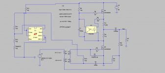
Adjustment with 10k resistor and 10k trimpot.
In my opinion 0.08V per turn is not fine enough, these suckers are super sensitive. I think we need to shoot for 0.04V per turn.
Change to 25Turn 5k trimpot
In my opinion 0.08V per turn is not fine enough, these suckers are super sensitive. I think we need to shoot for 0.04V per turn.
Change to 25Turn 5k trimpot
Attachments

Last edited:
Why the very low source resistor of the upper MOSFET?
Just fooling around with Nelson's ideas. I would set it up with 0.2 and 0.2 as originally shown.
I just forgot to change it back to stock configuration
Adjustment with 10k resistor and 10k trimpot.
In my opinion 0.08V per turn is not fine enough. I think we need to shoot for 0.04V per turn.
Hi 2 picoDumbs,
I appreciate this. Either way it's fine with me unless they are solid.
I hope there is no significant current through the gate. My 2SK180 gave me hard time because of this.. 🙁
- Status
- Not open for further replies.
- Home
- Amplifiers
- Pass Labs
- BAF 2015 Coverage