The triac will work to maintain the set voltage, so as the AC mains is low, it draws high current. It needs less current to allow full supplies as the voltage increases beyond that. I thik max current may be in the 60 VAC range on 120 V units. This is approximate. You could reduce the voltage setting and see the current draw fall.
1 ampere draw sounds too high. It would be a lot less with a 240 V unit in Europe from what we would see here.
Yup, left hand in pocket. 125 VDC will get your attention. It could kill you in fact.
Forget measuring the triac! Leave that circuit alone. Please! You have to float that section for starters (do not float the scope ground !!!!). It appears to be working properly.
Well sort of success.
Figured out the Headroom light issue. It came back after going full voltage. Q20 and its resistor.
Using my laptop as a signal gen. I was able to feed it a 1k signal and up the volume eniugh to output 1vrms on the amp.
Initial measurments looked good. With loads on the output, variac set to 60v, i had a decent wave form with the small crossover nitches explained in the manual.
Voltages seemed close withiut 7v of stated in the manual.
Current draw was less than .5 amps.
Increased variac to 120v and adjusted pot so the main caps had 112v on them. I opted to keep them lower than the manual for now, i have a fear of them blowing up in my face.
Triac firing looked better at 120 and a load with signal. Matched the pic pretty well as far as i could tell.
Thermal camera on both channels showed everytbing was heating up about the same. Two resistors on the faulty channel loooked to ve getting about 20deg warmer than the good channel but they were bit hot by any means (ill look more i to what those were later).
My main issue now, and not sure how to proceed, is when at full voltage with input and load as stated in the manual, i am pulling 1.3amp. The manual says it should still be under a half an amp.
My thaughts exactly. Find what's pulling the current. 2 resistors being 20deg warmer is quite a lot. If you can identify those it would be probably easier to find the smoking gun.
Have you checked idle? That transistor in idle circuit was blown, just replcing that one without any other things being off is enough amp might idle different.
Have you checked collector voltages on output transistors Q5 and Q6?
Cheers
Have you checked idle? That transistor in idle circuit was blown, just replcing that one without any other things being off is enough amp might idle different.
Have you checked collector voltages on output transistors Q5 and Q6?
Cheers
So i am confused what values i should be getting on these transistors.
Going between both channels, they are identical with exception to the temp.
I measured the voltage across the resistors that were getting warm and they were identical to each other. I think it was the auto detect hottest spot vs where my cursor was on the thermal cam. Did a better measure any they were the same.
The resistors that are getting hot though are not on the board lay out so i have no idea what they are. Layout shows a jumber.
When i measure the voltages on the transistors base to emitter beyween both channels, theyvare identical on most, but some are off .02v. Not sure of something this small could make a diference.
Moat measure in the .5v range base to emitter, but a few like Q1 and Q2 and they counter parts i was measuring 5.6v base to emitter, and Q4 and Q7 and they counters i measure 2.5 base to emitter.
Does this high voltage mean there are issues with these 4 pairs in both channels?
If they were on wouldnt i get .5ish base to emitter on them?
Thanks.
As far as transistor voltages go, if you have the same values all across both boards fault is not there.
What are the values of those two resistors which are running hot? It seems that is the only difference between the boards. Maybe photo would be helpful too. I have few of such amps here around, I can open one up if needed to identify the resistors.
cheers
What are the values of those two resistors which are running hot? It seems that is the only difference between the boards. Maybe photo would be helpful too. I have few of such amps here around, I can open one up if needed to identify the resistors.
cheers
p.s.
I don't have service manual on hand right now but have you measured idle. There is some sort of biasing procedure in there how to check it. I'm writing from my memory and I might be off but it is something like ''adjust trimmer to get 3mV across both emitter resistors''. Check if that is correct. And check that after few minutes when the amp warms up a little bit. If the voltage there is higher you have too high idle.
I don't have service manual on hand right now but have you measured idle. There is some sort of biasing procedure in there how to check it. I'm writing from my memory and I might be off but it is something like ''adjust trimmer to get 3mV across both emitter resistors''. Check if that is correct. And check that after few minutes when the amp warms up a little bit. If the voltage there is higher you have too high idle.
Yea the manual says to measure 4mv across one of the large resistors, it specifies which one, i forget the value, but it was the right side one. I set that on both channels as well as the pot to adjust the large cap voltage.
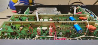
Attached is a pic of the resistors that were getting warm. They were about 150 deg which isnt all that hot i guess, but they are not on the board layout.
They are 2.7k value.
Not sure these are the problem though because both channels now seem to mearure from what i am seeing, identically.
30v across them resistors.
Line voltage at 120v
No input, 8ohm loads attached.
125v rail is 118v
80v rail is 73v
50v rail is 42v
-12v is -12.1
12v is 11.7
Attachments
Without looking at the diagram, just one comment. If the resistors are hotter, the voltage across them MUST be higher. Measure them against the other channel. Look at the schematic and use logic from there.
They werent hotter. It was an error on my part when measuring them. Both channels seems to be identical.
One other thing,
My current measure is coming from a killawatt meter in line with the variac.
Maybe i should desolder a lead at fuse and put my meter inline and measure current that way.
One other thing,
My current measure is coming from a killawatt meter in line with the variac.
Maybe i should desolder a lead at fuse and put my meter inline and measure current that way.
Those should be close enough. I measure the current entering the load, not into the variac.
The bias current measurement is the critical one unless you have a problem. Idle current draw is approximate and you are drawing peaks, not a sine. How each meter responds to this is not the same.
The bias current measurement is the critical one unless you have a problem. Idle current draw is approximate and you are drawing peaks, not a sine. How each meter responds to this is not the same.
Are my rail voltages close enough?
Seems the 50 amd 80 are a bit low. Perhaps something is pulling them down??
Or possible i have damaged but not toasted the primary of the gam coil and that is what is pulling the extra current?
Seems the 50 amd 80 are a bit low. Perhaps something is pulling them down??
Or possible i have damaged but not toasted the primary of the gam coil and that is what is pulling the extra current?

Honestly, I really doubt there is anything wrong with mag coil. I've never seen one bad. I've seen bad elcos and that caused strange problems but never blown mag coil. I've even seen blown rectifiers but again not mag coil. I would rule that one out really.
Is the amp working? Is just high current draw from the mains what is the problem? Try to measure it with some different meter. Analog one with mechanical instrument would be probably my choice. That current draw which is strange because of triac chopping the sinewave might disturb readings on some meters.
Is the amp working? Is just high current draw from the mains what is the problem? Try to measure it with some different meter. Analog one with mechanical instrument would be probably my choice. That current draw which is strange because of triac chopping the sinewave might disturb readings on some meters.
Ahh ok, thanks.
I guess i will have to Painstakingly go through each component and compare channels, hopefully something will stand out
I was able to feed a 1k signal in and chexking the output the signal looked good. I could not reach the 40v the manual wanted with my poor laptop headphone jack, but i was able to get to about 11v on the output and i got 3rd or 4th lights to light. Both channels were behaving the same.
Transformer was buzzing like crazy too. Shouldnt it be fairly silent?
First I would really check collector voltages on Q7 and Q4 those should be 80V at idle(or whatever your power supply is set) voltages on Q5 and Q6 which must have low rail which is 50V one. I would check idle on both channels, if moved I would re-adjust supply voltage and check bias again.
If all that looks fine I would first check both channels on the scope with no load, how it behaves, does it clip symetrically and so on. After that I would test it with dummy load and again observe the same things.
Those mag coils are noisy ones. Especially with the load it will buzz. If filter caps are bad it might be opening triac more trying to reach desired voltage but elcos can't hold it. It will cause mag coil to buzz even more. such case you can see the ripple on the scope. If those souble capacitors are defective that is quite some work to replace. There are boards available online where one board with 4 caps replaces those.
Resistors are R6 and R7
cheers
Mag coils can be noisy, uneven firing doesn't help.
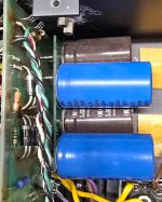
Those dual capacitors almost always fail. If they vent they make a heck of a mess. Bad caps will cause the mag coil to be noisy for sure.
Make certain the capacitors are name brand "snap mount" and the PCB attaches with posts and not wires. I've only ever seen cheaply made replacements. An insulator sheet between the PCB and capacitors.
I made my own with 2 oz copper, exact copies. I don't have spares unfortunately.
Colectors had same voltages as rails minus about a half a volt.
+/- 72v has 300mv ripple.
+42v has 450mv ripple
-42v has 300mv ripple.
What are R6 and R7 for?
Edit:
I cannot drive the amp to clip, i am going to need to find a preamp to feed this thing. My laptop cant drive it enough, but what i seen as far as i can drive it, both channels followed each other up to the forth led.
This is what was in the amp when i got it,Mag coils can be noisy, uneven firing doesn't help.
Those dual capacitors almost always fail. If they vent they make a heck of a mess. Bad caps will cause the mag coil to be noisy for sure.
Make certain the capacitors are name brand "snap mount" and the PCB attaches with posts and not wires. I've only ever seen cheaply made replacements. An insulator sheet between the PCB and capacitors.
I made my own with 2 oz copper, exact copies. I don't have spares unfortunately.
See attached.
Edit: Thanks for the heads up abiut the dual caps.
I have a working amp i am stealing parts from to get this working that has the dual caps.
When i find all the wrong, ill oder up the parts and some new caps for the other amp before i power it up.
Attachments
Last edited:
You're lucky. That appears to be a factory replacement kit. Mine looks the same. Notice the square pins to the PCB.
Normal radial caps and wire leads do not cut it.
You have the 3 ampere rectifiers still. Change to 6 ampere models. I only stock 600V and 800V units, you would be fine at 400V PIV.
I have to say, stealing parts from a working amp is the fastest way to end up with two non-working amplifiers. Never do this. Same for channel to channel. Just don't do that.
- Home
- Amplifiers
- Solid State
- Bad Carver M1.5 Power Transformer?