I would really advice to checking it using another meter. Some analog panel amper meter or something what yoi can get cheap. It is quite possible that both new meters can't handle signal produced by triac. Who knows what kind of meter they've used when writing the manual. I suspect there are really short current peaks which new instruments are detecting.
Check elcos of course. That is good idea.
Really if there would be such current draw there would have to be some sort of heat being produced.
I'm again thinking out loud. I must admit I've never tried to measure primary current at those amps.
Check elcos of course. That is good idea.
Really if there would be such current draw there would have to be some sort of heat being produced.
I'm again thinking out loud. I must admit I've never tried to measure primary current at those amps.
In the video posted of that guy repairing that carver, he was using the same killawatt meter i have mine plugged into. His read at 13watts at idle,
Mine is at 35watts idle.
So even if the meters are reading diferent that old analogs, mine is still pulling more than double what was displayed in the video using the same device. My dmm also shows the same as the killawatt.
So i dont really know. I dont have access to an old analog meter to verify.
I think my next move is to carfully tap into each secondary and see which one of them are pulling the current.
Im also going to remove the caps and try and measure thier esr. This amp has been powered down for almost 20 years so maybe they have dried out, i dont know.
Edit:
Im also going to increase the voltages on the large caps to manual spec and see what effect that has.
Last edited:
You have 35W at idle? That's ok really.
I thaught you have 1.3A primary current idle.
At that video there is super low consumption yes but later on he measures idle current which is like 10 times too low. After Tony adjusts it for sure it would be more.
Quick calculation and I'm just giving example and I might be off but it will be enough for general idea.
If you have idle of 5mV across emitter resistor that is at 0.5ohm 100mA.
There is 50V across output transistor at 100mA that is 5W od dissipation. You have 2 output transistors per channel and that would be 20W jist for that.
I think manual calls for a little bit less than 5mV though.
Also the rest of the circuit and also power transformer itself have some losses. If it is pulling 35W that would be perfect. But 1.3A is not 35W. Earlier, maybe yesterday I think you said it is pulling 1.3A. Might be though I messed up something.
I might have said 1.3. I dont remeber now, it was for sure over 1A, ill have to double check.
The wattage i got from thr killawatt meter like the guy in the video. Mine shows arox 35watts. The current i got from my meter and the killawatt thing, both showing over 1A(cant remeber what it was exactly now).
The wattage i got from thr killawatt meter like the guy in the video. Mine shows arox 35watts. The current i got from my meter and the killawatt thing, both showing over 1A(cant remeber what it was exactly now).
This is where things strange. 1A is over 100W if you are in 120V mains world and over 200W if you are in 230V area. That is strange. I'm not sure though if it can be because of power factor being somehow messed up. Also I don't know if elcos are weak if that could cause it. What I susspect is you have really short current spikes which are detected by your meters. But really I'm just guessing here.

Hi changedsoul,
It is extremely difficult to help someone when they are not using the methods and equipment set out by the factory. YouTube videos are something I would never rely on.
In a nutshell, if your supply voltages are all correct and your bias currents are correct, it should be drawing low current. Nothing should be getting warm beyond a couple dropping resistors in the power supply. Actual current draw depends greatly on your raw AC mains supply. We used high current variacs to make the supply voltage agree with the service manual. The triac firing should be even and constant.
Outside of those circumstances, we would have to have the amplifier on the bench in front of us to tell you more. There are many variabilities. Local oscillations in the amp sections can increase supply current. WHen confronted with questions, technicians relay on a body of stored knowledge and equipment so figure out what is going on (if anything). We can't guess without that unit being right no front of us. We can guess, sure. That may do you more harm than good.
Some manufacturers restricted service and service information to trained people for very good reasons. It wasn't to hide secrets. It was to reduce destruction. This is very true in the case of Carver. At least you get it that your mag coil is good.
Whatever you want. Ask 🙂
I recently did the recap of my Carver M 1.5t and being skilled manually it was easy to do. seeing the xray video made me wonder if the bias and voltage regulator are in their best configuration. I ask: mine is 230V, what value should the bias have if I measure it as per the video?
he talks about a correct value between 3.5 and 3.6 mV
thankyou
Bias current doesn't change with the supply voltage.
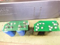
The dual capacitors should be replaced with something equivalent to the Carver factory replacement PCB. Capacitors on leads simply will not cut it, if that was done, take them out and do it properly. Note that Carver service never supplied the PCBs only, it was a complete assembly and I still have one (which will not be sold). I make exact duplicates for my own service use. The boards need the heavy pins, not skinny leads.
- set supply voltages and let them become stable.
- set bias currents, allow them to settle and correct as needed.
The dual capacitors should be replaced with something equivalent to the Carver factory replacement PCB. Capacitors on leads simply will not cut it, if that was done, take them out and do it properly. Note that Carver service never supplied the PCBs only, it was a complete assembly and I still have one (which will not be sold). I make exact duplicates for my own service use. The boards need the heavy pins, not skinny leads.
@anatech
this is clear. However, I asked what the correct bias value in mV to maintain with the 230V version is and it could be the same as the 110V - but I wanted confirmation. Is it possible to see your complete kit that you have?
you have M 1.5t?
( Why don't I see the ""Quote button in your post?)
ops, now there is. ok
Last edited:
The bias current is dependent on the DC supply voltages, which should be about the same for any amplifier type, 120 VAC or 220~ ~240 VAC. To do a conversion you only need to make sure the DC supply voltages are what they should be. So to be clear, the bias currents between those versions is identical.
I was Canadian Factory warranty for Carver and still repair them.
Pics. One is original from Carver, the other is what I make.
I was Canadian Factory warranty for Carver and still repair them.
Pics. One is original from Carver, the other is what I make.
Attachments
@anatech
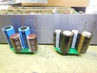
if you repair them you will know many things about my Carver M 1.5t. my recap version is hybrid, two caps directly on the motherboard horizontally and two resting on the chassis vertically with a copper cable, as I saw someone do from images found on Google. if you think my version is wrong, I'll open a new topic, post a photo of my work and give me more advice.
if you repair them you will know many things about my Carver M 1.5t. my recap version is hybrid, two caps directly on the motherboard horizontally and two resting on the chassis vertically with a copper cable, as I saw someone do from images found on Google. if you think my version is wrong, I'll open a new topic, post a photo of my work and give me more advice.
Hi jeffrowland,
It is very simple. Build this highly engineered amplifier the way the factory built it. They created an extremely reliable amplifier, and it was teams of engineers who did it. Not one guy.
I'm sorry. I am not about to critique someone's build. I know how to build them properly, and improve them a bit as well. There are so many ways for these amplifiers to go wrong if you change them, I figured them out and know enough to tell you that improving one and making real improvements is an engineering issue. Your average audio improvement guru hasn't got a clue. I've had to undo enough hack work from these people to know.
Let's put it simply. In order to improve any amplifier, you have to know it at least as well as the team that designed it. That excludes most people for any brand. True, some brands are designed poorly. You still have to know at least the same amount as the people who created it in order to improve or comment on it. Those engineers were university trained and most modification angels are not.
I would be interesting to see how you will do it. Though I feel trying to improve PM/M1.5 probably makes no sense. It is what it is. You either like it or you hate it. I like those how they are but I have to admit I'm not using it for hi-fi. I have no need for such power. My speakers are big relatively lazy AR9lSi and I'm driving it with EL84pp. For me it's loud enough and it sounds good. I have plenty of loud gigs on the menue all the time amd at home I prefer things to be a little bit quieter. Still I would ne interesting to hear back from you how it will turn out.
We are here on diy audio forum, it is about building, fixing and sharing experience. I'm also all in for ''right to repair'' and I'm really glad that Bob Carver decided to publish manuals. Thanx for that really. It saved me plenty of time. Do you want to ''improve'' you amp? Great, why not. I remember years ago when I've painted my LandRover black matt using roler. People thaught I was crazy but in reality I'm going to do to my car whatever I want. Same goes to my amps of course. I'm not saying Carver is some sort of black magic which only few people understand how it works but I would dare to claim it is a little bit complicated than your average 50W hi-fi amp.
Here again words of caution. Keep one hand in the pocket when playing with those. There is 240V between those two big elcos there and trafo is capable over 1kw. It can kill you. It is not like digging inside HAM radio SB220 amp but still dangerous enough.
I would also like to hear what Changedsoul will find out. I might be even tempted to plug one of mine amps and measure idle. I've never tried it. I only have one problem which is the same one as Anatech mentioned. Time. It is very limited thing which you can't even buy...
Ok, I remeasured using the procedure in the repair manual (Voltage adjust pot fully CW (min voltage))
My line voltage is 123v before the variac.
Manual states to bring variac up till triac just fires(about 60v).
Well mine fired at 53.
KillAWatt says its pulling .21A which seems correct.
Both lower lights are lit and fault light is out.
Apply a 1k signal and increase amplitude until amp output is 1vrms.
Check and check.
Output waveform looks a bit sketch and my 125 voltsge is not close to 57v, mine is at 31v dc with the triac firing at 53vac(just when it fired).
Triac amd diac waveforms look just the manual images.
Ok, so manual says triac should fire at about 60vac so let me bump the variac to 60vac.
Variac is now at 60vac and the speaker output waveform looks much better.
My current draw now is at .4A on the killawatt and the triac and diac waveforms look the same.
The 125v supply is still low at 49vdc, should be 57ish
80v should be 35, i have 30v
50v should be 16, i have 17v
12v supply be 11.2, i have +10.8 and -11.8
Now at this variac voltage, i am unable to move the pot to have any effect on the 125v supply. I tried to see if i could bring it to 57, but it has zero change.
I feel like there is an issue with the 125v and 12v supplies, i just dont understand the schematic enough to locate it...if there is even a problem.
I havent connected a speaker to this yet, but driving the amp before when i previously set the supply voltage, i was able to push a 1k signal though to abiut 4 lit leds, and the output on the scope looked nice.
Someone mentioned popping the top off one of theirs and taking a few mesurmemts, that would be awesome if it could get done.
When ever time permits of coarse.
Hi Tajzmaj,
I can tell you that everything in the Carver amps was engineered, even op amp current can cause trouble. My advice is really important. Do not change them unless you have much more experience and are capable of engineering. Also understanding why things were done the way they were. Many times people assume engineers did things to be cheap. Ahhh, no. Often various things were done to make it reliable, and others because throwing money at it would not improve performance one little bit. That is called engineering. Just because a part has possibly better performance on the data sheet, it may not in that circuit. or there are other characteristics that impact the circuit. This is where "modifiers" who know better fall down often. That and they waste money for no benefit. Some changes really improve things, others don't do anything at all. All cost money, some may cause trouble and make an amplifier like a CArver m 1.5 unstable. Op amp changes will do that sometimes.
Were they the best sounding amps? No. Although I really like the Lightstar series one, and the TFM-75 a lot, they were great amplifiers.
Hi changedsoul,
What I wrote above applies to everyone. It also applies to more or less degree to all audio products. The very first thing you have to do is respect the choices the designers (as long as they were engineers) made. Very few people are smarter than a team of engineers. Certainly no one who really knows what they are doing does YouTube videos. They have not got time.
The way we actually test these loosely follows the manual. There is some variance between individuals of a model due to component variations. One thing we do not do is look at triac waveforms unless we have a problem in that area. Otherwise there isn't any point. Therefore, we've never written down voltages at various input voltages - and they are approximate. There are many quick checks we make depending on what we see as we power up. I can't hope to detail everything and would probably forget some. A lot is done between the ears of a good technician that no one sees externally. So, it "looks" easy.
The voltage adjust at the low input voltages doesn't have any or little effect. The triac is nearly full on, you can't turn it on any harder in that circuit. So don't sweat that. Increase the AC mains voltage and monitor the high rail, and keep it below your set point until you reach your normal mains voltage, or the mains listed in the manual if that is low. You will notice it decreases slowly over time (or should). OVer a long time period that voltage setting may increase, so you may want to check it every few years to make sure it hasn't climbed too high.
Don't get fancy, don't attempt to out think the designers. it won't go well for you. I constantly have to clean up after self proclaimed "Geniuses". Sometimes they damage foils and make troubleshooting far more difficult, and certainly raises the cost of service. I love it when they short between pads.
DIY is for designing your own stuff or building a kit. DIY is not servicing. For that you need training and equipment - plus a work ethic. I encourage DIY, big time. But the term "DIY" doesn't give anyone license to do things they don't understand and damage equipment. People get that confused. They also don't like it when it costs more money to clean up the mess, that's when good, repairable equipment hits the trash or gets gutted.
@changedsoul
@Tajzmaj
@anatech
(alla faccia)², but how much do you write.
² it's a nice interlayer when jokingly indicating someone who exaggerates. It's a lot to laugh about here 🙂
and then don't worry, I care about my beloved Carver which, among other things, plays very well and plays great with the Jeff Rowland Model One.
I'll see you later while I open my topic specifically for the recap.
thankyou
- Home
- Amplifiers
- Solid State
- Bad Carver M1.5 Power Transformer?