To stay safe probably I would just stick 340 and 350 inside. Also check resistors around those transistors. There are some relatively low resistance ones around there which sometimes go open when transistors go short. I think it is 91 ohms or something.
Hey Anatech,
I'm runing relatively big fleet of those Carvers. It must be 40 or 50 amps. I must admit at some point I've lost the count. Main racks are PT2400/PT1800/PM950(newer black ones which are running hf drivers). It is 8 such racks. I have 4 aditional with 2 PT2400 in each just to power some more subs when needed. PM1.5/PM1.5a/PM1200 I have 4 racks of those and in each there are 4 amps. Those are used for wedges only. Since I have enough of those it is always 1 channel of the amp one 8 ohm wedge only. I try to avoid running those amps on 4 ohms. Can it take it? Of course it can just I don't like doing it. I tend to be gentle with all my gear. I even never run anythig to absolute maximum. I think that last 2 or 3 dB makes no sense. If it is not enough I rather bring few more speakers and amps. I'm the one buying recone kits 🙂...
Besides those ''main racks'' there are some amps in various racks for smaller systems and even some amps not racked but just sitting there and waitting to be used 🙂
One more comment on Carver being unreliable. I'm using those amps for last 25 years. Many I bought on various Ebay and similar siites. Many I bought totally fried. Blown outputs...dry capacitors, even some missing parts and so on. You know what I mean, ebay special ones for 60usd. Ater cleaning, fixing, and so on I've only blown one channel on PM1.5, onjly one channel out of all those amps. Ir was my fault. We were in a hurry to connect system for some demonstrations. I manafed to hook 2 amps into the same speaker, you know there are 2 speakons at the back and instead of linking 2 speakers together i plugged another amp inside. All it happened was one of the amps went in protect. Later at home on the bench I've discovered only one blown output transistor and that's it. Carver even when you do something stupid and when it dies the damage will be in most cases very local. It won't fail catastrphically.
Totally different one are those unfortunate EV P3000 amps where when it goes it really do it with proper show. Those fail catastrophically with holes in the pcb and all that jazz.
Really about Carver, one thing I probably like the most is how reliable it is. If you treat it well it's going to run for decades. Thanx Bob !
Cheers, Taj

P.s.
Since I've fixed many of those amps I have to confirm one more thing. Bad mag coil? I've never seen one. Even the ones in PT amps which tend to run super hot and some develop burned through outer insulation, even those I've never seen bad one.
Since I've fixed many of those amps I have to confirm one more thing. Bad mag coil? I've never seen one. Even the ones in PT amps which tend to run super hot and some develop burned through outer insulation, even those I've never seen bad one.
Hi Taj,
Any Carver amp will be perfectly happy with a 4 ohm load. No problem.
One thing that will kill the series like the PM 1.5 is running high power, high frequencies. That will lock up the commutators and keep the output stage at a higher voltage level, probably resulting in thermal runaway and failure or shut down. They are designed to run either full range, or bass. Not just mids or just highs. Low line voltage could possibly kill the triac, then all hell breaks loose. Hopefully the fuse blows soon after.
You're right. Any normal failure mode causes the power supply to shut down pretty quickly. Energy is limited, losing one output only is common. Carver amplifiers don't kill speakers in a fault mode. They do end speakers that can't handle the real power they put out while operating normally. We had so many idiots kill Klipsch LaScalas on PM 1.5's. These are 375 watts per channel, a LaScala is 104 dB/watt efficient. How loud do you need things to be? I was also doing warranty for Klipsch at the same time. This is by no means a knock against Klipsch, they were honest about max SPL and input power.
Didn't have many issues with PT amps or Lightstar (series 1). The stuff just ran. Problems were more old age things. Fix them and off they go. One other thing I have seen. Feedback resistors burning out in Lightstars before modification. They couldn't handle the dissipation run with a sine at full power. That isn't music. We fixed it.
I have repaired the fried transistor and the fried resistor that was on the emitter and the fault led no longer lights, yay...but now thr headroom light turns on after a short time with no inputs and variac only up so 50v rail is at 5v.
I wasnt able to find a scenario for that in the manual.
Anyone know what might be causing this?
Its only a songle channel mis behaving
I wasnt able to find a scenario for that in the manual.
Anyone know what might be causing this?
Its only a songle channel mis behaving
You have commutator transistors and diodes. You also have driver transistors and other possible damaged parts.
Also check bias, your biasing circuit might get fried, Q17 would be first one to check if q13 went shorted. Also R21, Measure collector voltages on outputs and commutators to see if something is out of the wack there. Blown commutator will result in higher voltage on the next stage down and output stage would heat up at idle.
And please be careful, voltages there are high, between 2 high rails there is 250V! It can kill you. Any shots done by probes will result in more damage and so on.
And please be careful, voltages there are high, between 2 high rails there is 250V! It can kill you. Any shots done by probes will result in more damage and so on.
One thing to watch Taj. The voltage tends to rise over time. Set it a touch low, in fact I normally set to 118 VDC and check it. It will start higher and fall, but over time component drift will probably increase it. The filter caps are 130 VDC.
Why do I set for 118 instead of 125 VDC? It may be years before I see it again, and sometimes there local mains are higher than where we are. Replace that trimmer also, with a single turn, good quality pot. The difference in power isn't much, and if those main filters vent, good luck finding new ones. So from a practical viewpoint, I am protecting the customer and equipment without impacting performance that much.
How are yours running? I am not familiar with the 240 V versions, component drift may be different. I know the triac firing components have different values. Check them warmed up.
I'm also setting it a little bit lower yes. Also some amps which I've bought were already robbed of filter caps and those are unobtainium. I designed board to fit paralelled snap in elcos. It works well enough and elcos used are 160V.
When I'm servicing one of those I always replace all trimmers with the same style ones so I can use original trimmer knob to be able to adjust it from the top. I clean and reflow solder joints on those nasty hot resistors on the power supply, I replace all those small elcos there around which are boiled from those resistors. In general I usually replace all the elcos in those amps sine it is there from early 90's mostly. I also take outputs out, clean and replace the ''goop''. In some of the amps I have to resolder collector connections of the output transistor sockets. And in all the amps I replace those nasty fans with modern ones. This last part sadly takes frolling 2 small holes to the back and modifying resistors in the fan drive circuit.
After all that done amps are good to go for many years. As far as component drift goes I can't really judge because when it comes to bench usually goes through complete service. Thinking off it might be yes that some are showing up a little bit high. Than again mains here went up in last 25 or 30 years. It was normal to be 225V but today it is more 235.
Yes of course I check it warmed up. Not just voltages but also bias and all that. I have sort of ocd when it come to that 🙂
Components around triac are different of course. Voltage is higher here but also frequency is 50hz which plays the role here. I must have converted 20 of US amps to our line voltage always with no probles.
I like those amps. I really do. I even like working on it though I must say I don't have no problems with it at all. I only work on it when I can't resist and I buy another one from somewhere and I need to restore it.
I find some of the power supply resistors go out of tolerance. For anything important, I use good metal film. The hot ones on the right side near the RCA end, I mount on the other side so they don't cook the capacitors above them.
They can be improved for better sound quality / lower distortion. That is involved and you have to work on them for HF stability.
They really are a good design. Maybe not the lowest distortion or noise, but a lot better than many out there in that power class. They are more reliable for sure.
Replacing those dual capacitors is a real pain. Also, change the diodes to 6 ampere models, they are 3 ampere from the factory. This is a factory recommended change.
Your modification boards for the main high voltage filters is the road I would go. I'm going to bet the voltage regulator went high on those units. Those were very good capacitors.
Yes of course I'm replacing 3A diodes. Always. You have to ''stack'' them somehow but it can be done nicely. I always remove trafo secondary while doing it, I clean old flux and inspect situation between the pads there and at this point I replace those dual caps with my board. It is a pain since there is not much of space under that input board. Honestly that board with pcb mount xlr connectors is the only thing I don't like that much. That could be done better but it works and since I'm not using it for hifi I really don't care if it is a little bit noisy.
Thank you for your concern. I am not very comfortable around high voltage but I know enough to respect it and be very cautious.Also check bias, your biasing circuit might get fried, Q17 would be first one to check if q13 went shorted. Also R21, Measure collector voltages on outputs and commutators to see if something is out of the wack there. Blown commutator will result in higher voltage on the next stage down and output stage would heat up at idle.
And please be careful, voltages there are high, between 2 high rails there is 250V! It can kill you. Any shots done by probes will result in more damage and so on.
Q17 was bad and I commandeered it from a working amp to keep going down the troubleshoot path. R21 was also ok.
I decided to take a chance and removed the jumper from the triac and slowly brought the voltage up until the triac fired. it buzzed a bit to much for my taste....but increased the voltage a bit more and to my surprise the headroom light went out...but I was drawing some near 7 amps from the plug and I shut it down.
Went to the section about excessive current draw with no signal applied and after triac fires (VII).
Im not sure what to do here. First check is the steering bridge. I checked them a while ago...de-soldered one side on all diodes and they checked good.
Next is checking the diac and triac but Im not really sure how to check these.
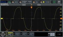
See attached screen shot.
This was taken across the diac....grounded on the triac gate, and probe on the other side, line voltage.
Looks nothing like the image in the service manual (Fig1). but then again, Im not really sure how to measure a triac and or diac with a scope.
Can anyone lend a hand?
Second Attached is the image of the triac, oscilloscope grounded on MT1 and probed on MT2.
They look nothing like the manual, but then again, I am pretty sure I am not probing correctly.
Thanks for all the help.
Attachments

Hey,
I guess the mechanism of failure was like this.
Probably output was shorted at full power, that caused overcurrent situation and if you look closely you will see those mpsu transistors must actually drive big TO3 drivers(Q8 and Q3). It does happen quite often (at least from the damage I've seen on some amps which I've bought and fixed) that outputs and drivers survive but actually those VAS transistors kick the bucket. After that one was shorted full rail(124V or whatever it was set) on bias network, killed Q17 and I would not be surprised if Q20 and R55 would be damaged too. That is npn VAS transistor and it's emitter resistor. I would also check drivers, outputs and commutators(that is all TO3 devices). You can usually detect shoted one in circuit. You can compare measurments between channels and see if something looks dodgy without actually pulling it out just at the beginning.
More to your question now. To me it looks like triac is opening all the time. It looks like really trying to build up supply voltage but it can't because there is some really high current draw from it. Have you confirmed all the rails are coming up? Nothing is shorted? You need to see 3 supply voltages. +-35, +-75 and +-124. That is roughly. I've forgotten which amp you are fixing. I'm looking at PM1200/1.5a service manual. Your amp might be a little bit different. I know some amps have lower rail at 50V and so on. But you get the idea.
I would short the triac maybe and open it just a little bit. I would be measuring all the voltages. Ratios between them should be roughly the same even at really low values or at least all should be comig alive. Maybe open variac to get maybe 5V at the lowest rails and that will give you something between 10 and 15V on the high rail which on those big elcos there. If one of the rails is missing or it is not really coming up you have either shorted elco or more likely shorted bridge rectifier. For lower 2 rails you have diodes there where trnsformer wires connect to the board. Those are pain to replace. If high rail is out there is bridge rectifier mounted close to those 2 big elcos. I've seen those shorted several times.
Do not open variac too much. As you know ''mag coil'' is not intended to run full throttle like that. But still it is just transformer and you should get a little bit of something on all rails and it should be more or less in the ratios like lower rail is the lowest there is something in between and high rail obviously is the highest. There will be current draw at low rail for 12V supply also, when things start to ''wake up'' at low voltages there might be that things will be off...but you get the idea what I mean.
I might be really off but that is how and what I would check. Also I apologize if number of parts are messed up or something. It is 6 in the morning here and I've just returned home from mixing late gig.
Best regards
You should see that increasing the AC voltage drops the current draw. Your draw seems high though.
Use an external DC supply to power up the top rails and look for excessive current draw in the output section. The triac is pretty reliable, as is the drive circuit. I don't know what you have for available power supplies and instruments.
Use an external DC supply to power up the top rails and look for excessive current draw in the output section. The triac is pretty reliable, as is the drive circuit. I don't know what you have for available power supplies and instruments.
I think the output rails are ok. Shorting the triac and using a variac to bring the 50v rail up to 10v, i have on my rails
10v, 18v, and 29v, all plus and minus.
I have virtually zero current draw from the mains, less than .1amp.
Using the working channel as a reference i began checking Vbe on all the large transistors bolted to the chasi.
The only ones that differed were Q5 and Q6.
Q7 and Q4 were the same on both channels.
I got low voltage (.2v) on Q5 on the bad channel as opposed to .38 on the good channel.
And for Q6 i got 0v Vbe on the bad channel as opposed to .18v
I checked the 4 diodes going to the base of Q5 and Q6 and they look good.
Q7 on both channels see to be on with a Vbe voltage of .6v.
Diode D13 that is tied to the emitter of Q7 and the collector of Q6 is good, as the compliment D23 for Q5 and Q4.
If Q8 or Q3 were suspect i would think Q7 and Q4 would not be on, and the readings were the same on the good working channel.
This schematic and repair manual is rough trying to decipher one ink blob from the next 🤣
One thing i noticed though now that i have repaired the DC offset on the output,
My IC1 still has a output of 6.7v on pin 6, with nothing on its inputs pin 2 and 3. Well pin 2 has a input value of .03v and pin 3 is zero.
I would not think these inputs should not produce an output on pin 6 of 6.7v...maybe this IC is toast?
Edit:
I forgot to mention, i pulled Q5 and Q6 amd tested with a meter and they looked good. Nothing shorted or open. Seemed to check like a normal transistor.
Also, i dont have a way to power up the secondaries with a dc supply.
Increase the voltage until you begin to draw current. Not excessive. Then you can see where the current is going. Check bias currents and DC offset voltages and compare to the other channel to see what is normal.
Don't jump to conclusions. Circuits will not operate normally until they have reasonable supply voltages. Check you have at least 4 ~ 5 VDC for each op amp supply before even looking at them.
Don't jump to conclusions. Circuits will not operate normally until they have reasonable supply voltages. Check you have at least 4 ~ 5 VDC for each op amp supply before even looking at them.
The op amps had 8v plus and minus on them when checked.
I will bump the voltage up u till i see current draw. Maybe a thermal cam can point me in the right direction.
Thanks.
I will bump the voltage up u till i see current draw. Maybe a thermal cam can point me in the right direction.
Thanks.
Hi, quick one. I'm behind the mixer again, be aware lifting up the voltage won't work up to full rails. "Mag coil" will hit heavy saturation way sooner. I don't konow exactly when but I think in my cormer of the world with 240V primary side configuration it will happen at around 50V. After that point which Indon't know where it sits in your place current draw will rise really fast really high.
Don't take any advice here for granted. We might be wrong. We just share our experience and thaughts. Coukd it be defective triac still? Of course. I've seen it. Rare case but it does happen. If you have another one try it. Probably for test even smaller 16A one(to220) would do something.
Can op amp die? Of course. It will be a pain to get out but if you feel so replace it. Those first two transistor after op amp might fail or develop leak also.
All those are scenarios which are extremely rare though. I think I've replaced only one op amp in 25years in one of those.
Again, keep one hand in the pocket.
Bringing the amp up to higher voltage caused the headroom light to go out on the faulty channel.
I slowly raised the voltage while watcbing the 125v rail voltage and it got up to 120 before i was even at full line viltage 😬.
I ended up adjusting thr power board pot all thr way Clclock wise to minimise voltage as much as i could...raised the variac up to full volts and my 125 was in no danger of blowing up my main caps.
I took a leap of faith with the headroom light out at full voltage and decided to plug the amp in straigt to the mains while watcbing the current. (It wasnt high with the variac).
Plugged straight in, the current was abiut 1 amp. I dont have a signal generator so i need to fine a way to feed it a 1k signal. It was not at the less than half an amp draw, but its not the 7 i had before.
I know something is not right still because the one channel headroom light being on at lower voltage. Maybe now thats its able to power up and i have no dc offset, i can further test with a load and signal and hopefully that will point me towards what is still faulty.
Thank you all for the help this far. This has been a good learning experience for me.
As for the fireing of the triac,
Was i measuring it correctly?
Ive ready you need can only measure triac with dual channel scope.
- Home
- Amplifiers
- Solid State
- Bad Carver M1.5 Power Transformer?