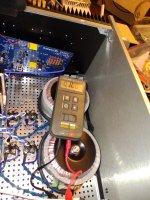
Fired up just the power supply. It works, but unloaded is a touch high. At 120 volts on the variac it measured 39 volts.
I know this is unloaded but was still a couple volts high. No big deal, if anything might require a touch less bias so good so far.
Magic wand seemed to work, couple minutes after power cut, it was still measuring 39 volts. After magic wand it was 4-8 volts.
I used 10 gauge wire with pin end connectors for the power supply to boards and they are like solid bars (pre shaped) now after soldering the connectors on each end.
To comply with the suggestion of putting 3 amp slo-blows in those lines temporarily for fire up, I dont want to cut those heavy lines so
I guess I will put an inline fuse holder to link to boards form the end of the pin carefully, and reattach correctly afterwards. Also still need to correct the input
grounds before final test.
Russellc

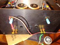
Couple thoughts before switch flipping, I rigged the input lines to board by leaving extra length on both the neg and pos inputs to board.
The negative input line goes in -input hole, comes back through from back side of Ground hole. This makes the permanent connection for
the negative in, as well as leave a post sticking up for the positive to temporarily ground to. Seems like the shorting plug in the input accomplishes
this, but such assumptions is where I mess up.
The other question is the beginning setting for pot that controls bias. Instruction is: " P2 set to max value - check with probes across unpopulated Rt, that one being in parallel with P2; that way pre-set is min Iq"
This is pretty plain, but just in case, I take this as set pot to highest value (ohms) for lowest bias reading, right? I once misread instruction not so plain and did opposite! Using a variac, so caught the sudden rise and corrected, but was a warning. This instruction fairly clean here!
Pots currently reading 240 ohms or so, needs set to highest value. Setting them up, they maxed out at .509k ohms and .487k ohms. Being dual mono and having put an extra fuse for each side at A/C input, I plan to remove fuse from side not being set so it can be performed channel at the time.
Russellc
Last edited:
Well I have ooked something, power supply I think, or same error in both channel, tried both. Variac goes up, green lrd lights up, Bias not coming up very fast, but offset easily nulled. Then fuse blew, 70 volts or so from variac when it happened. Puck were about 30 degrees. One of the main fuses, 5 amp slo blo
Tried other side, same thing identical. All parts were heating up...oh well! Nothing burnt, got brow or smelled funny, hopefully minor issue.
Ideas welcome, dont know where to begin.
Russellc
Tried other side, same thing identical. All parts were heating up...oh well! Nothing burnt, got brow or smelled funny, hopefully minor issue.
Ideas welcome, dont know where to begin.
Russellc
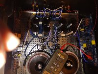
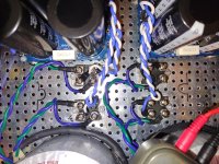
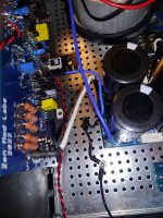
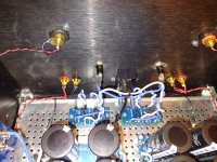
pictures of your setup could help
did you set Iq trimpot all the way CCW?
did you had DVM set to mVdc across 0R11 resistor group and what value you had there when fuse poofs out?
silly question - just pops out, you have pucks in proper places (not swapped)? No silly question in fact, I did it once on my T-Bed but luckily got it even prior mounting pcb on top of them
that's why I now have a habit using red marker on positive rail outputs and black (or blue) on negative rail outputs - just to prevent making same mistake
Will take some pics. What ever, same with both sides.
Pots were set to max, and was slowly coming up with variac, twiddling knobs, little more. Then the led went out.
As to outputs, I will check, but think I asked here and was pretty paranoid and was triple checking...on the other hand that would explain both sides. I have checked all the 3 legged small devices and they are oriented correctly (according to silk screen) but will check with light and helpers to make sure correct part in correct place.
And will recheck outputs. That would be just my style. Check, double check, ask, recheck and then screw it up anyway.
Russellc
Oh, the bias. It was just starting to show, second time, really low .08ish, I think the first time I applied power I was around .7, I powered down and thought I would swap fuse to other side and if it acted same, fire up whole amp
Came back after re rereading other posts here decided, no I should get channel all the way up then the other, but fuse blew before or around 70 volts on the variac dial, so approximate
Came back after re rereading other posts here decided, no I should get channel all the way up then the other, but fuse blew before or around 70 volts on the variac dial, so approximate
Well don't know if this problem, when I "adjusted jumpers" earlier and fit tried them I left them in place! Instructions were to start without them, then plug in when running on good percentage of bias right? Would that have caused all this mayhem and ruined every part with my luck.
Rereading post #1
Rereading post #1
I'm sorry, the highest was .078 ish. Yeah 6.3 should have tanned or smoked something.If you were measuring 0.7V across the 0R11 resistor group, thats 6.3A
The hottest the outputs measured was 27 C.
Rethinking, I am sure it was .7 at highest, but I neglected to specify mV!If you were measuring 0.7V across the 0R11 resistor group, thats 6.3A
Well don't know if this problem, when I "adjusted jumpers" earlier and fit tried them I left them in place! Instructions were to start without them, then plug in when running on good percentage of bias right? Would that have caused all this mayhem and ruined every part with my luck.
Rereading post #1
this is not a problem
leaving that jumper ( JP1) out initially, is for your convenience
putting it in place later, after initial adjustment of Iq done, and doing DC Offset adjustment is practically as cherry on top - to optimize input LTP operating conditions
after that, you can leave it in place or pulling it out
recheck everything trice, without applying power
pics, please
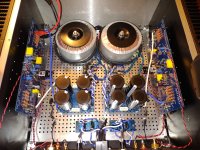
Ok, checked output positions, looking at board, the "30p" unit is on the right hand side, "50p" unit is on left. Looking at schematic, M2 = the 30p unit on the right, so I got that part right.
Attachments
-
 IMG_20240318_070322338.jpg591.1 KB · Views: 40
 -
 IMG_20240318_070331811.jpg737.4 KB · Views: 38
 -
 IMG_20240318_070233865.jpg625 KB · Views: 40
 -
 IMG_20240318_070346226.jpg664 KB · Views: 45
 -
 IMG_20240318_070417719.jpg782.1 KB · Views: 46
 -
 IMG_20240318_070301613.jpg397.4 KB · Views: 47
 -
 IMG_20240318_070306488.jpg605.9 KB · Views: 41
 -
 IMG_20240318_070425656.jpg609.1 KB · Views: 41
Will check all positions, especially bd parts. I thought outputs was main concern. Are BD parts the two stuck together on heat sink?
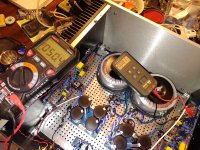
Meter is showing .107. ideally, this should be up to .180, or am I way off and should be 180 without the decimal point? Outputs are at 32C right now, barely warm.
Meter is showing .107. ideally, this should be up to .180, or am I way off and should be 180 without the decimal point? Outputs are at 32C right now, barely warm.
care to give some details now, except throwing numbers?
where is each DVM connected (Iq, DC Offset), and what is happening now - did you reach full mains voltage and amp is stable, or fuse popped again?
no need to fiddle with DC OFfset at all until you get Iq dialed in, and even then it is possible on lu with JP1 installed in place
so, please be clear with new info, I'm easily confused
- Home
- Amplifiers
- Pass Labs
- Babelfish XA252 / Babelfish XA252 SIT / Babelfish XA252 SET