well , I'm not following you ........ 0.3db down at 20K and 0.1db at 20 , ref to 1KHz - that's pretty standard for wakoo simple amps
of course one can use it wherever it suits
of course one can use it wherever it suits
Hi ZM, just following on from your post #45, where you are talking about kits. I have a good stash of original Toshiba 2SK170BL fets, and would like to use these - do you think you will be able to make available just the bare pcb's for sale?
If so when would they be available and do we access that via your website?
regards,
Gary..
If so when would they be available and do we access that via your website?
regards,
Gary..
yup, why not , and you're second - asking the same
my goal was to make damn thing in a way that Greedy Boyz can use less golden Toshibas (read : N type , instead of P type)
so , expect soon to see kits in Trade forum , in 3 levels :
-bare pcb (I will solder smd caps and MMBF5486) ,
- pcb with all SMD , including input 2SK2145BL,
-pcb with all SMD , including input 2SK2145BL, plus all parts on pcb , including IRFP150
that OK?
You should add the option to receive a video of the baby being conceived, er, the PCB being assembled. That's worth a few extra bucks.
😉
😉
had enough scare in my own workshop , no need to watch cheap horrors


just joking , of course ...... instantly thinking of Ping! machine
OK , will add option 4
just joking , of course ...... instantly thinking of Ping! machine
OK , will add option 4
Last edited:
Thanks ZM, the 1st option with bare pcb and presoldered SMD caps and the MMBF5486 fet will be just fine for me. Looking at your circuit, I make that 3 off SMD caps per channel.
you need better one , than old brain and bad memory?
besides fact that they're P channel parts , so adequate for not-flipped FE
though , I did exactly that iteration first , but wanted to be more as Brave Mickey Tailor , so not enough Giants killed with one stroke
see attached (that one maybe need few optimizing details , not sure are all values are correct (not just copy-paste-edit later) ...... sorry for big file sizes ,posting from workshop and shrinking is not handy on this PC
anyway , moved to presented iteration , as being further from simple cloning .... and that's so boring , besides being rude when done in public
have any other comment , regarding present iteration ?
🙂
edit , and yes - I still have 450++pcs of J271 , same as J309
Attachments
Last edited:
Since single output, it should be no problem to go without lower mos source resistor like the ACA.

I think the J2 design also has a side in exploration of balance. The gain control was shifted towards the front FET by doubling the input jfets, reduction to only a single output gain device and change from Aleph CCS to mu follower stage. I suspect that there is a sonic related reason that Papa kept the source resistor of the lower output FET. Playing around with several values may be rewarding.
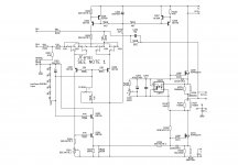
In the post #89, the new schematic (looks like Papa format - nice!) the Q209 and Q210 are shown as IRFP240 but it should be IRFP150 or something with 'enough' transconductance is that correct? The IRFP240 needs to be paralleled otherwise stick with SS or IRFP150 or can single 240 actually be used?
Last edited:
Eagle is stupid
or I am stupid
🙂
pinouts are the same for these two and there is no IRFP150
so , I'm editing that later ........ I wrote that schm is raw , regarding values and names , meaning - it isn't checked for same
so , IRFP150 , no doubt ...... again - that's two IRFP240 in one case
and it's cheap
and no matching , here
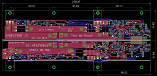
btw. form factor of pcb is same for that one and pcb in post #1 - UMS compatible
or I am stupid
🙂
pinouts are the same for these two and there is no IRFP150
so , I'm editing that later ........ I wrote that schm is raw , regarding values and names , meaning - it isn't checked for same
so , IRFP150 , no doubt ...... again - that's two IRFP240 in one case
and it's cheap
and no matching , here
btw. form factor of pcb is same for that one and pcb in post #1 - UMS compatible
IRFP260 & IRFP264 have a higher transconductance, current rating and power dissipation. Just that the capacitance is too high. But with input JFET 'twins', would it be possible to drive these devices?
IRFP260 & IRFP264 have a higher transconductance, current rating and power dissipation. Just that the capacitance is too high. But with input JFET 'twins', would it be possible to drive these devices?
see that thingie , on which lower mosfet's gate is connected ?

current there is in range of 18mA ......
Attachments

Last edited:
- Home
- Amplifiers
- Pass Labs
- Babelfish ᄅſ....or FW J2 on Steroids .... or Not your Father's J2!