Hi gents.
I'm simulating the boxing of my SissySIT, and need some advice.
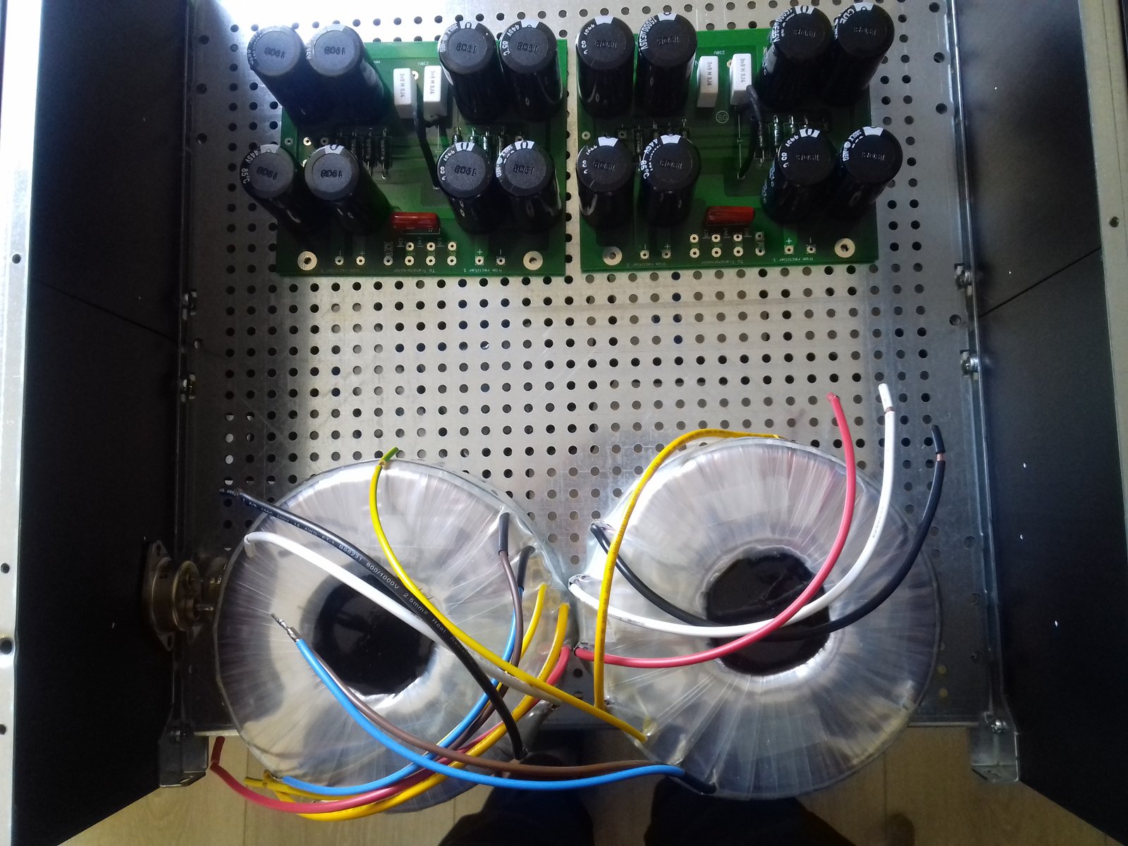
My trannies are big boys, and fill almost all the width of my 4u 400 case.
How would you guys place the parts?
In the picture, the two white points beside the trannies show where I want to mount the Tokin. But doing so will put theit big legs at a few mm from the transformers.
Is it acceptable? Both for heat and noise?
Thanks!
I'm simulating the boxing of my SissySIT, and need some advice.
My trannies are big boys, and fill almost all the width of my 4u 400 case.
How would you guys place the parts?
In the picture, the two white points beside the trannies show where I want to mount the Tokin. But doing so will put theit big legs at a few mm from the transformers.
Is it acceptable? Both for heat and noise?
Thanks!
acceptable
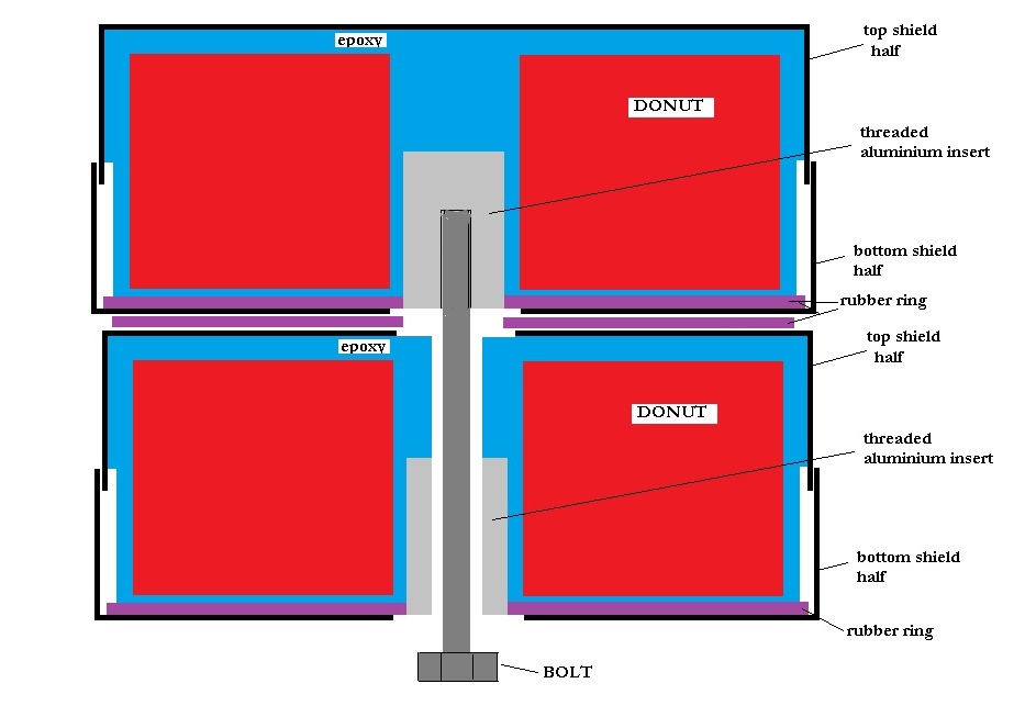
though , can you put big boyz stacked vertically ?
it's easy to drill one black core all the way, and use longer bolt
something as I did here , and even simpler - you don't have pots to care about isolation etc. : post #52 , Most Greedy Boy, of them all... or (there is no) DEFiSIT of Papa's Koans
that way , you'll have space for bridges at left and right of Donuts
also , use some spacers between lower frame L brackets and base plate , to allow some space for routing mains wires beneath
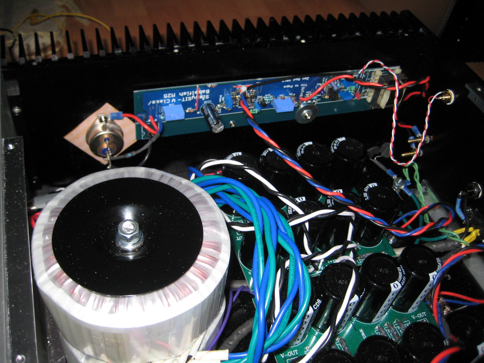
Here is a picture of my SissySIT with stacked Antek transformers. I purchased a length of threaded rod and cut it to size, with nuts at both ends to bolt the transformers in place.
Thanks!
I'll explore the stacking option.
ZM, I don't need to route the mains below the perforated baseplate.
I have FW like PSU boards, with a path for mains live and neutral, along with CL60. Looks pretty straightforward to provide mains to the transformers without any hassle.
I'll explore the stacking option.
ZM, I don't need to route the mains below the perforated baseplate.
I have FW like PSU boards, with a path for mains live and neutral, along with CL60. Looks pretty straightforward to provide mains to the transformers without any hassle.
Fellow builders, please point me toward a suitable PS board/boards for SissySIT. I want to finish my build and like to order the last parts I need. I already have the case, transformers, boards populated and SITs.
Is this usable? Ebay item #323452303840 Other suggestions welcome.
Is this usable? Ebay item #323452303840 Other suggestions welcome.
Last edited:
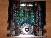
I've mounted them vertically in my Alpha build, it's also a 4U 400 case.My trannies are big boys, and fill almost all the width of my 4u 400 case.
How would you guys place the parts?
The most delicate part was drilling/tapping 8mm in the 10mm front panel for the transformer bolt without getting peeping holes.
Next time I will mount an L-bracket for the transformers on the bottom plate, this will give me less stress 🙂
Fellow builders, please point me toward a suitable PS board/boards for SissySIT. I want to finish my build and like to order the last parts I need. I already have the case, transformers, boards populated and SITs.
Is this usable? Ebay item #323452303840 Other suggestions welcome.
It appears to be the same as the ones that I used. They were purchased from an ebay merchant.
Attachments
I have some 22uF polymer organic low esr caps. Can they be used for the 6N139 mod? Maybe also for C1/C2 (BD139/BD140 supply)?
if you like idea of using them, and they have enough voltage (16 as minimum), they're the best!
🙂
🙂
Am I wrong saying that all the trimpots except Iq cannot be measured onboard?
(to verify prescribed settings)
(to verify prescribed settings)
they all can be measured on-board
what's important!!!!!!! is, practically, "just" two of them - lower trimpot ( R6, that one leaning to negative rail) in JFet buffer - need to be maxed , and output Iq setting trimpot (P1) which need to be minimized
other two trimpots are not critical regarding starting value, if you follow proper setting procedure ( removed jumper between input buffer and xformer, no load on output)
if you're having trouble deciphering how to check them in situ from top of pcb, either look back in the thread ( covered with sketches) or buzz , and I'll dig them again and post here
Thanks, I've got the pictures for the two Iq ones.
I'll take a deeper look.
By the way my Cinemags are stuck in some airport somewhere, so plenty of time before first power.
Today I'll test the PSUs!
I'll take a deeper look.
By the way my Cinemags are stuck in some airport somewhere, so plenty of time before first power.
Today I'll test the PSUs!
Here is a picture of my SissySIT with stacked Antek transformers. I purchased a length of threaded rod and cut it to size, with nuts at both ends to bolt the transformers in place.
Hi Ben. I was thinking of stacking transformers. I see the metal pad on the top, but is there also one in between the transformers?
- Home
- Amplifiers
- Pass Labs
- Babelfish M25, SissySIT - general building tips and tricks