OK.
I did a test - first time with source (sonos connect) attached to RCA: open jumper, 9.3mA offset. I have a note on my sheet 23V offset at jumper? Maybe I wrote that down wrong?
Oops, forgot to short input.
Test again, this time with input shorted: ~22ma, adjust P6 to get 20mA. OK. Offset at jumper was ~3V. Turn P7 to reduce, I ended at 2.78V with P7 clicking. No more turns to go.
Power down and check with mighty ZM before continuing...
OK.
I did a test - first time with source (sonos connect) attached to RCA: open jumper, 9.3mA offset. I have a note on my sheet 23V offset at jumper? Maybe I wrote that down wrong?
Oops, forgot to short input.
Test again, this time with input shorted: ~22ma, adjust P6 to get 20mA. OK. Offset at jumper was ~3V. Turn P7 to reduce, I ended at 2.78V with P7 clicking. No more turns to go.
Power down and check with mighty ZM before continuing...
well, besides me not being sure for each number what you're writing (mA, mV, V ??!?), I'm just going to presume things
so , you did set Iq of buffer to 20mA (which is 20mV across R8)
now, you need to set DC offset of buffer , fiddling with R7 (trimpot) to get as close is possible to 0V ( preferably no more than few mV, + or -)
be sure that you're taking measurements on proper jumper pin - that one looking at buffer output ; find which one it is - simply with beep test while amp is powered off - search for beep! with one side of R5
I believe there is post with appropriate snips from pcb layout, but in short - for both channels - pin closer to heatsink side is pin connected to buffer
just in case - for that measurements - means red probe at said pin, black probe at GND , wherever is convenient to get it, best at pcb GND pads

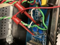
can't see from picture - R4 and R5 are 39R?
what's range of DC offset from end to end of R7 trimpot?
what's range of DC offset from end to end of R7 trimpot?
R4&5 are 39R
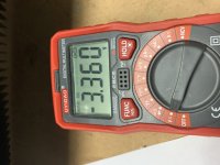
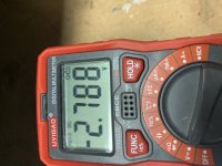
Buffer offset voltage at extreme ends of P7 are -3.36V and -2.79V. Not mV
The amp has worked in the past, and was on the shelf for several months. A friend was running it all day when the channel stopped working. I looked at the bottom of PCB, everything looked OK there.
Buffer offset voltage at extreme ends of P7 are -3.36V and -2.79V. Not mV
The amp has worked in the past, and was on the shelf for several months. A friend was running it all day when the channel stopped working. I looked at the bottom of PCB, everything looked OK there.
Attachments

compare ohmic measurements across R5 between channels, of course with amp off
confirm that ohmic span is between 0R and ~28R from end to end of R7 trimpot, on misbehaving channel
(which fool did leave R designation for trimpot, anyway)
confirm that ohmic span is between 0R and ~28R from end to end of R7 trimpot, on misbehaving channel
(which fool did leave R designation for trimpot, anyway)
remove jumper, feed 1V or so in channel input, observe is there any difference between buffer input and output (same pin where you measured offset)
write here
write here
I completely forgot - can you check voltages at BD emiters - that would be any end of RB and any end of R8
2SK182ES THF-51N Triode V-FET SIT Free mailing activities, due soon, friends in need, book in advance
I completely forgot - can you check voltages at BD emiters - that would be any end of RB and any end of R8
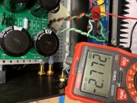
Voltage at Rb = -2.77V
Voltage at R8 = -23.2V
Attachments
Working channel is R8 at -10.3V and Rb at +10.3V
Next test:
Voltages at other pins in BD139 and BD 140.
Working Channel
Voltages on both sides of R9 = 23V / 11V
Voltages on both sides of R12 = -23V / -11V
Not Working Channel
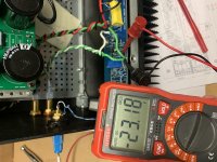
Voltages on both sides of R9 = 23V / 12V
Voltages on both sides of R12 = -23V / -23V
Dead BD140? 10k resistor failed short? I have 10k's in my stash, I can try that...
Next test:
Voltages at other pins in BD139 and BD 140.
Working Channel
Voltages on both sides of R9 = 23V / 11V
Voltages on both sides of R12 = -23V / -11V
Not Working Channel
Voltages on both sides of R9 = 23V / 12V
Voltages on both sides of R12 = -23V / -23V
Dead BD140? 10k resistor failed short? I have 10k's in my stash, I can try that...
Last edited:
oh yes, we found it
it must be some Gremlin ( wrong step during assembly and testing the amp)
never had one of these exact BD transistors dud - they're made in so big quantities and for so long that there are no bad ones
sorta same as 6SN7 in tube world - everyone had time to learn how to make them properly, 'cause demand was so big and long
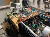
BD139/140 20 pack arrived from Amazon. I had 15 mins before a work video meeting so I swapped the BD140. Quick test on R12 voltage drop looked good. I'll do a more thorough test later.
Since I have the lid off, and I have the updated bias circuit parts in a box, I think it's time to do that work, too. Then my friend wants to borrow the amp a while more. I think he will be done with it when I make him a Singing Bush.
ZM, I need to convince him that a full kit is a better option. Stay tuned and I'll paypal you once I finalize that. I will likely go for 2 full kits.

Still a problem. I forgot to compare voltage at Rb between channels. BD139 also had a problem. Swapped it. Voltage looks better when comparing left to right. Set IQ and offset. Super. Play test music through test speaker. Works!
speaking strictly of cascode voltage level :
comparing voltages of one vs. second channel - just to verify that they're in ballpark
say that 300mV of difference is nothing to write home about
300mV from top of my head- even 500mV will not urge me to investigate - even to crunch some numbers (mV, mA, Beta)
comparing voltages of one vs. second channel - just to verify that they're in ballpark
say that 300mV of difference is nothing to write home about
300mV from top of my head- even 500mV will not urge me to investigate - even to crunch some numbers (mV, mA, Beta)
- Home
- Amplifiers
- Pass Labs
- Babelfish M25, SissySIT - general building tips and tricks