The culprit was a bad crimp connector at the transformers.
That is the only connection i would still recommend crimp. I several times had cracked solderjoints at rectifiers with that thick solid core tranniewires. It is like a plant breaking through concrete : )
best
st.
cut solid core close to Donut, solder multistrand to them
that's the reason why I'm always ordering Donuts with flexible wires
been there, done that, pain in the ....... back side
that's the reason why I'm always ordering Donuts with flexible wires
been there, done that, pain in the ....... back side
I have limited experience with such builds and after seeing some lovely build of many FMs including Zen Mod I'd like to confirm/ask a few (rather basic) questions regarding wiring and mounting for the SissySIT and get some insights from the pros.
1. It is preferable to have static and magnetic screen on the Toroid.
2. Mains -> Fuse -> Transformer
My guess is we go by 10 Amps max and voltage? So 20AWG? Stranded will be more flexible?
2. PSU -> PCB and PSU caps (power wires)
24/22 AWG? Stranded? UL1007?
3. Signal wires e.g RCA terminals -> PCB
- Gauge: 24 e.g twisted pair CAT5 wire or UL1007 24AWG?
- Shielded or not: Unshielded twisted pair fine for short runs? Shielded if you are paranoid?
- Stranded vs Solid: Matter of preference. Solid keeps shape but stranded more flexible.
- PVC vs PTFE : PTFE tolerates heat better for soldering but stiffer and difficult to deal with. Matter of preference?
4. Other wires (e.g SIT to PCB)
Same as PSU -> PCB?
5. PCB -> Speaker binding posts.
18-20 AWG?
6. Any other wires I'm missing (hidden below base plate)?
7. Are the PSU->PCB and PCB->Speaker terminals soldered on the PCB end or connected via male-female connectors? In some pics it appears as if there are connectors.
8. Can the PCB be mounted using either 10mm/5mm standoff?
In ZM's post #671 (page 8) he seems to have used same black wires here and to power the boards and for the speakers and also in this beautiful build on his blog https://www.zenmod.in.rs/wp-content/uploads/2019/06/IMG_20190603_200707-1024x509.jpg but the wiring to PSU caps looks thinner.
I would choose 16 AWG for power, speaker and ground, but it would be a little overkill. Belden 9497 is one of the popular choice. I have been using Mogami shielded 26 AWG mic cable for input signal.
Last edited:
8. The standoffs for the SissySIT board should be the same height as the Mosfet thickness as the Mosfet is mounted between the heatsink and the board. This keeps the board from being bent and stressed.
Be sure to check that the component leads and wires are clipped short so that they do not short against the heatsink.
Be sure to check that the component leads and wires are clipped short so that they do not short against the heatsink.
Thanks plasnu. May be it is ok to use 22AWG since it seems rated at 7A.
Thanks for that critical info Ben. The datasheet indicates thickness of 4.58mm-5.31mm. I saw ZMs pic of the MOSFET sandwiched between the PCB and the heat sink. So with the keratherm I guess 8mm standoff might give that snug fit.
Thanks for that critical info Ben. The datasheet indicates thickness of 4.58mm-5.31mm. I saw ZMs pic of the MOSFET sandwiched between the PCB and the heat sink. So with the keratherm I guess 8mm standoff might give that snug fit.
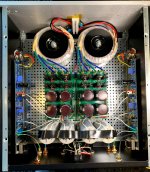
I finally finished my SissySIT after it was put on hold because COVID and being in California for almost 5 months. Back in February I had the amp completed and was on the last adjustment and could not get R7 on the left channel to make any changes. I did some troubleshooting and it appeared that the resistor was bad. I ordered a new one and never got a chance to swap it out until yesterday.
After swapping the resistor I was able to get the amp dialed in and it played music. I only have a couple of hours on it, but is sounds really good to my ears and I could not be happier with it.
ZM thank you for a great design and making it available to all of us.
After swapping the resistor I was able to get the amp dialed in and it played music. I only have a couple of hours on it, but is sounds really good to my ears and I could not be happier with it.
ZM thank you for a great design and making it available to all of us.
Attachments
Last edited:

BRN, Pictures please.
What chassis did you use?
How many volts are the rails and how many amps did you settle with?
Also, what is the temperature rise on the heat sinks?
Rush
What chassis did you use?
How many volts are the rails and how many amps did you settle with?
Also, what is the temperature rise on the heat sinks?
Rush
BRN, great news
for all troubles - as always - blame Mighty Moi
for all Green - as alway - blame Pa
just don't tell him , easily uppish .........
for all troubles - as always - blame Mighty Moi
for all Green - as alway - blame Pa
just don't tell him , easily uppish .........
Rush,
I used the Modushop steel Dissipante 4U 400mm.
I believe they are about 24V each. the amp is dual mono and I'm using 2 Antek 18V 300VA with the CRC Power Supply (Class A amplifier) and a pair of 50uF film caps per supply.
I don't remember the temp, but it is a little warmer than the M2C, but not so hot you can't touch it.
I lent my 2nd SissySIT to a friend, and he was thrilled with the sound. "Best sound in his system". He's been running F5 Turbo V3's, Aleph J's, F5, or Bryston 7BST's. He was loving it until the left channel went quiet. He said nothing went boom, no magic smoke, no smell. I just got the amp back. PSU voltage is good. Ammeter on negative wire to each channel looks similar. Nothing looks burnt. No loose wires. Jumper looked OK, but I swapped one anyway. Sound of the channel is very quiet and crackly. I'll need to dig in and do some more poking around when I get free time - maybe this weekend. Any ideas?
Also - my friend is wondering - is there a 50-100W SIT Turbo amp design anywhere? He would consider unloading his F5 V3 Turbos for SIT Turbos!
check continuity of autoformer windings
while poking, put some fuses in rails, to prevent costly mistakes in troubleshooting
do you have a scope?
while poking, put some fuses in rails, to prevent costly mistakes in troubleshooting
do you have a scope?
besides Singing Bush, there is lhquam's SIT amp
maybe one day I'll have time to try something in same range of power and Push Pull (not SE as Singing Bush)
maybe one day I'll have time to try something in same range of power and Push Pull (not SE as Singing Bush)
Yes - I have a scope. and signal generator.
check Iq through input buffer (1R resistor) and DC offset at jumper
if OK, apply some signal and check is there the same at opened jumper
then close jumper and check signal at output of autoformer (Silmic)
- Home
- Amplifiers
- Pass Labs
- Babelfish M25, SissySIT - general building tips and tricks