That's a very useful tip. Thanks for sharing!Here is a construction tip:
For those diyers like me with no room to store a drill press, a drilling guide made by Big Gator Tools works great in helping me drill holes in heat sinks for tapping. It helps to keep the hole perpendicular to the heat sink, and also the tap perpendicular when starting tapping.
I have found that for large heat sinks when I am not able to clamp the drill guide to the heat sink, I just press the drill guide against the heat sink with one hand and hold drill in the other hand.
The drill guide is not cheap, but it and the hand held drill takes up way less room than a drill press.
I have built three amplifiers using the drill guide to drill and tap the heat sinks, and am now working on my fourth. It works for me.
Drill Guide - Standard V-DrillGuide 1/8"-3/8"
This is the one that I have:
MINI V-DrillGuide
ZMod,
Boards arrived safely. Can’t wait to start working on them, just need to order a few more things and a move before I can start.
Ben Mah,
Thank you for the tip. I just ordered the drill guide for myself.
Brad
Boards arrived safely. Can’t wait to start working on them, just need to order a few more things and a move before I can start.
Ben Mah,
Thank you for the tip. I just ordered the drill guide for myself.
Brad
Another useful tool is a stepped drill bit. They come in various sizes and they are great for drill larger diameter holes. I have used them to drill holes to mount large diameter on-off switches and for cooling holes.
I use masking tape to cover the metal to protect the finish and to provide a surface to mark out the hole locations. A centre punch is used to put a dimple in the drill locations to accurately locate the drill bit and to keep the bit from wandering. With the dimple, the drill bit is accurately located even if the hole location is obscured by the drill guide.
I use masking tape to cover the metal to protect the finish and to provide a surface to mark out the hole locations. A centre punch is used to put a dimple in the drill locations to accurately locate the drill bit and to keep the bit from wandering. With the dimple, the drill bit is accurately located even if the hole location is obscured by the drill guide.
Another useful tool is a stepped drill bit. They come in various sizes and they are great for drill larger diameter holes. I have used them to drill holes to mount large diameter on-off switches and for cooling holes.
I use masking tape to cover the metal to protect the finish and to provide a surface to mark out the hole locations. A centre punch is used to put a dimple in the drill locations to accurately locate the drill bit and to keep the bit from wandering. With the dimple, the drill bit is accurately located even if the hole location is obscured by the drill guide.
Plus 1 for stepped bit, they work very well. I was afraid they would be a jerky nightmare, but not so. Cut very smoothly between steps, even going all the way through the very last step if required.
Russellc
If anyone waiting on cinemag gets an update, please do post it. I'm resisting the urge to call and check since they're just building these as a community service....
Trying not to be a pain in the ***.
Trying not to be a pain in the ***.
If anyone waiting on cinemag gets an update, please do post it. I'm resisting the urge to call and check since they're just building these as a community service....
Trying not to be a pain in the ***.
I was not notified. Mine just showed up one day.
Rush
I was not notified. Mine just showed up one day.
Rush
Yep. I got a heads up from the UPS tracking (address is registered at UPS) and the credit card charge (notifications are setup). Mind you this was several months back, but all my orders from them have worked out this way. Nice folks, great products.
BK
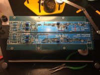
Got my boards today. They look great! That should be everything I need to finish the build. Getting my build sequence / process together now. Can't wait.
Thank you, ZM!
Thank you, ZM!
Making some great progress. 😀
ZM - The board layout and your instructions are excellent. Thank you! Made 2 dodo errors (Installed D2 instead of D5 on one board and swapped R16 and R19). Fixed after verifying against schematic and the BoM I made.
Question. I am attempting to follow very closely for the setting of the Pots during installation. I have R6 and R7 set referencing R4 (28ohms across) and R5 (0 Ohms across) accordingly. I have P2 set to mid point at 10k even though it is not too important.
I am struggling with how to set the 2K P1 pot. In post #603 ZM is very clear re: how to handle R6 and R7. Then it is mentioned for P1 - "confirmed with ohmeter...whichever way you find adequate".
Could someone provide guidance re: how to properly set P1 to 0 Ohms? I have not found it in the thread, so please forgive what is most likely an obvious question. I have not installed VR1 or anything further than the pots in ZMs guide in post 1.
Much appreciated!
Attachments
Last edited:
If you look at the schematic, P1 is located between Pin 1 of OK2 and R15/VR1. Put the ohmmeter probes at those two locations and measure. Adjust P1 back and forth to confirm that you are changing the resistance, and adjust P1 until you have zero resistance.
"whichever way you find adequate" was written taking in account possibility that pcbs are already on heatsink and that you're checking P1 fiddling with pins of neighbouring parts
that's usually tin foil hat time , needing some staring at goats and schematic , to decypher which parts and which leg of these are exactly connected to P1

in case when pcbs are still free to mingle in hands , simply put probes between solo pin and (now soldered together) pair of pins of P1
simple as that
that's usually tin foil hat time , needing some staring at goats and schematic , to decypher which parts and which leg of these are exactly connected to P1
in case when pcbs are still free to mingle in hands , simply put probes between solo pin and (now soldered together) pair of pins of P1
simple as that
.........
ZM - The board layout and your instructions are excellent.........
really nothing of my own accomplishment
in reality , I'm mimicking Papa all the time
while he's mimicking Roger Corman
Attachments

You're welcome.
It is the front of board answer and Zen Mod provided the simpler back of board answer.
"So whichever way you find adequate".
Zen Mod's doesn't require the tin foil hat, goats, and schematics though. 🙂
It is the front of board answer and Zen Mod provided the simpler back of board answer.
"So whichever way you find adequate".
Zen Mod's doesn't require the tin foil hat, goats, and schematics though. 🙂
ZM and Ben Mah - LOL!
ZM - I should have thanked you too for the reply in #951. Silly me didn't see it from the phone. I should have looked at the traces on both sides of the board... DOH!
I am starting to get a much better grasp of the goat whispering required to understand a schematic. 😀 A bit of reading online and a few classes is serving me well to start understanding. Who says old dogs can't learn new tricks.
As I learn, the DIYAudio community has my gratitude for helping me not blow up parts or burn down my house. That keeps a happy wife and happy life.
Next step is to finish up the boards, get a proper set of taps, and maybe get the tool or something similar Ben Mah mentioned in #940 to mount the SITs. Sadly, until I get a different / new chassis and build another PSU, the M2x boards will be giving up their home to the SissySIT for a short time.
I was reading the situation dBel84 had, so I need to be sure to check the rail voltages. My original plan was to just use the exact PSU from the M2x. However, from my M2x build notes, I was well over 25V unloaded. This circuit calls for 24V, and it seems to be sensitive to higher voltages, correct?
Last edited:

Oh - thank you, ZM. I put in the sockets, so I can swap. I wasn't sure what the characteristics were re: the differences, so I went with what was behind door #2. 😀
- Home
- Amplifiers
- Pass Labs
- Babelfish M25, SissySIT - general building tips and tricks