You can find the templates in the DIYA Store. Here is the link to the page that has it in PDF. UNIVERSAL MOUNTING SPECIFICATION

@randytsuch
post #2, here : https://www.diyaudio.com/community/...bstrd-aka-m2-gone-berserk.325038/post-5489363
UMS applies
put them on 1/3 of htsnk height, starting from bottom
post #2, here : https://www.diyaudio.com/community/...bstrd-aka-m2-gone-berserk.325038/post-5489363
UMS applies
put them on 1/3 of htsnk height, starting from bottom

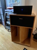
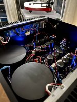
Looks great!Time for the lid to go on and bake for a while 😁
Mighty @Zen Mod, is a Mini Dissipante 4U400 suitable for this Fish (of course with a plus cap bank) when the PSU is an external unit?
all of my small amps are suitable for 4U/400, with or without PSU in it
big amps being just few ..... Singing Bush and Lazy Singing Bush, Babelfish XA252, Babelfish Aleph XJ
practically, if amp is mine and you see 24vdc nominal rails, Iq up to 1A8, 4U/400 is Swiss Knife
big amps being just few ..... Singing Bush and Lazy Singing Bush, Babelfish XA252, Babelfish Aleph XJ
practically, if amp is mine and you see 24vdc nominal rails, Iq up to 1A8, 4U/400 is Swiss Knife
Zen Mod… Aleksander… 🍻🍻🍻🍻🍻!!!! And thx to Pa as you say!
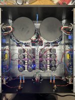
It’s up and running and sounds amazing. Super spooky.
It’s up and running and sounds amazing. Super spooky.
Attachments

Fugly!
silly amp is happy driving those!
it'll burn in for some time, expect full happiness in 100hrs or so
silly amp is happy driving those!
it'll burn in for some time, expect full happiness in 100hrs or so
I did something dumb. Instead of leaving well enough alone, I decided to redo the whole biasing sequence after the amp was on for a while.
When I put the multimeter across R8, R6 (pot) does nothing. R8 reads 1.6mv. Do I assume the pot is bad?
When I put the multimeter across R8, R6 (pot) does nothing. R8 reads 1.6mv. Do I assume the pot is bad?
Actually it’s worse. It’s both pots on one side that (R6, R7) do nothing when turned. Pots will only click in one direction. The other side is flawless.I did something dumb. Instead of leaving well enough alone, I decided to redo the whole biasing sequence after the amp was on for a while.
When I put the multimeter across R8, R6 (pot) does nothing. R8 reads 1.6mv. Do I assume the pot is bad?
cool it down, remove jumper between buffer and autoformer
set R6 trimpot (which Fool named trimpot with R, instead of P??) to max ohm readout across R4 - somewhere around 23-24R (39R//100R)
set R7 trimmpot arbitrary in middle position; confirm with ohm readout across R5
power up again, observing (mili)voltage across R8, set to 20mV rotating R6, set 0mV at jumper (buffer output pin) rotating R7
all ref. to schm in post #1
if/when everything OK, put jumper back
Across R4 I am getting 0.0mv. Do I need a new pot?cool it down, remove jumper between buffer and autoformer
set R6 trimpot (which Fool named trimpot with R, instead of P??) to max ohm readout across R4 - somewhere around 23-24R (39R//100R)
set R7 trimmpot arbitrary in middle position; confirm with ohm readout across R5
power up again, observing (mili)voltage across R8, set to 20mV rotating R6, set 0mV at jumper (buffer output pin) rotating R7
all ref. to schm in post #1
if/when everything OK, put jumper back
Something is off I can get much higher than 23-24 ohms across r4 on the r6 potI said Ohms
meaning amp is powered Off while measuring resistances
Maybe I did something wrong earlier, i got like 80ohm, now it’s max ing aroumd 30ohm (p6,across r4)
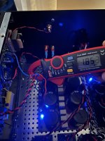
But when I then pwr on, i can only get a reading of 1.5-1.7mv across R8 no matter how much I turn R6Maybe I did something wrong earlier, i got like 80ohm, now it’s max ing aroumd 30ohm (p6,across r4)
first carefully (with probes, easy to slip ) confirm that you have around +11Vdc at top of buffer and -11Vdc at bottom of buffer
for lower one - any side of 1R resistor
for top one , RBR resistor ( as I see , you have original/starting iteration of pcbs)
ref. to GND (black probe to GND), nomenclature by schm in post #1
for lower one - any side of 1R resistor
for top one , RBR resistor ( as I see , you have original/starting iteration of pcbs)
ref. to GND (black probe to GND), nomenclature by schm in post #1
RBR to gnd is 10.64v, side of R8 to gnd… 0.5vfirst carefully (with probes, easy to slip ) confirm that you have around +11Vdc at top of buffer and -11Vdc at bottom of buffer
for lower one - any side of 1R resistor
for top one , RBR resistor ( as I see , you have original/starting iteration of pcbs)
ref. to GND (black probe to GND), nomenclature by schm in post #1
- Home
- Amplifiers
- Pass Labs
- Babelfish M25, SissySIT - general building tips and tricks