check your soldering around Q2 ...every solder point, R11, R12, C2
you don't have negative rail to buffer
Q2 C is connected to negative rail, so negative rail voltage
Q2 B is at 1/2 of negative rail
Q2 E must show approx 0V65 less than base, and that voltage must be present practically at R8
just in case, triple check that you have BD139 at positive rail (Q1) and BD140 at negative rail (Q2)
also, be sure that you didn't forgot to put Mica isolator for each BD transistor, with some goop
no need for plastic bushings (hole in BD isolated) but with pair of them being on same heatsink, you must use Mica at back of at least one
no need for plastic bushings (hole in BD isolated) but with pair of them being on same heatsink, you must use Mica at back of at least one
Mica on Q1 and Q2? Q4 is on keratherm. Checked solder on q1 and q2 any anything near there.also, be sure that you didn't forgot to put Mica isolator for each BD transistor, with some goop
no need for plastic bushings (hole in BD isolated) but with pair of them being on same heatsink, you must use Mica at back of at least one
check voltages at Q2 pins, post #2081
you must be able to trace voltage, to find point where you have it and point where you don't have it
be careful with red probe, if you slip and make short, damage is unavoidable
you must be able to trace voltage, to find point where you have it and point where you don't have it
be careful with red probe, if you slip and make short, damage is unavoidable
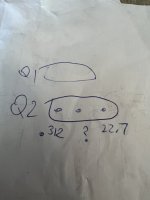
For Q2 only one pin reads ok. See photo. And the center pin goes bezerk. I can’t get a stable measurement. At one moment 0L, at another a flash of a reading.check voltages at Q2 pins, post #2081
you must be able to trace voltage, to find point where you have it and point where you don't have it
be careful with red probe, if you slip and make short, damage is unavoidable
Attachments
I was going to order some new bd140's just in case. However, I see bd140-s, -stu,-16,-10 in the part number and now not sure which are ok?
whichever
investigate PCB and parts, what's wrong - you must have 1/2 rail voltage at Base - there is 10K going to GND and 10K going to negative rail
use your ohmmeter for some troubleshooting, that's basic routine ........ check trace from base to resistor, then resistor itself, then trace from resistor to negative rail ......... simple as that
regarding BD 140 suffix - irrelevant in this case
though, I'm taking -16 whenever I can get them , way of getting controlled (higher) Beta
whichever
investigate PCB and parts, what's wrong - you must have 1/2 rail voltage at Base - there is 10K going to GND and 10K going to negative rail
use your ohmmeter for some troubleshooting, that's basic routine ........ check trace from base to resistor, then resistor itself, then trace from resistor to negative rail ......... simple as that
regarding BD 140 suffix - irrelevant in this case
though, I'm taking -16 whenever I can get them , way of getting controlled (higher) Beta
Attachments
confirm polarity of C2, positive must be aligned with mark on pcb, thus positive connected to gnd
if that is OK
remove Q2, test it with diode tester or in any other way known to you
then check 10K resistors (R11, R12) with ohmmeter
confirm with ohmmeter that one end of R12 is connected to negative rail , other end to R11
confirm with ohmmeter that one end of R11 is connected to gnd, other end to R12
when looking at BD 139/140, letters to you, legs down, then you have ECB from left to right
something is not logical even with your Q1, which is supposedly operational - there must be difference between B and E voltage ; if you have something around Rail/2 voltage at B, then you must have 600-700mV lesser voltage at E
The buffer is FIXED 😁!!! Thank you once again! I replaced the two pots (they didn’t stop on one end, just spins), and I replaced the BD 140 and 139 (one showed up as a resistor in my mega 328 tester, and the other had very different values than the bag of new bd’s).confirm polarity of C2, positive must be aligned with mark on pcb, thus positive connected to gnd
if that is OK
remove Q2, test it with diode tester or in any other way known to you
then check 10K resistors (R11, R12) with ohmmeter
confirm with ohmmeter that one end of R12 is connected to negative rail , other end to R11
confirm with ohmmeter that one end of R11 is connected to gnd, other end to R12
when looking at BD 139/140, letters to you, legs down, then you have ECB from left to right
something is not logical even with your Q1, which is supposedly operational - there must be difference between B and E voltage ; if you have something around Rail/2 voltage at B, then you must have 600-700mV lesser voltage at E

Good work! The Mega is a great little analyzer for $15.The buffer is FIXED 😁!!! Thank you once again! I replaced the two pots (they didn’t stop on one end, just spins), and I replaced the BD 140 and 139 (one showed up as a resistor in my mega 328 tester, and the other had very different values than the bag of new bd’s).
The buffer is FIXED 😁!!! Thank you once again! I replaced the two pots (they didn’t stop on one end, just spins), and I replaced the BD 140 and 139 (one showed up as a resistor in my mega 328 tester, and the other had very different values than the bag of new bd’s).
trimpots are spinning in both ends, some not clicking at all, some clicking just on one end, some clicking on both ends
so, only ohmmeter can confirm is trimpot OK or not
all trimpots I'm sending in kits are checked
now, what you really did to loose negative rail, I can't figure out from information you gave
anyway, it's OK now, that's what counts 🙂
Thanks.@randytsuch I used vernier calipers, marked with pencil then drilled and tapped.
I ended up making my own template, and taping it to the heatsink. It worked well, all my holes are where I wanted them to be 🙂
Used visio to make it, took a few tries, but got it right eventually.
The good old UMS Spec is what you are looking for. Print it and tape it to heatsink then punch or mark the holes for drilling.Maybe a longshot, but wondering if anyone has a drill template for drilling out the heatsinks? To locate the 4 holes to mount the board to the heatsink
I'm ready to make holes, and was going to use the PWBs to mark the hole locations, but thought it would be better if I had a template to use instead.
Thanks
Randy
Cheers,
Stephen
Thought I would share the progress I am making on my SissySIT R.3 . After assembling the boards, Quasimodo led the way on the R value for the Snubbers. Scratching a particular diy itch, I decided to go with a Hammond 159ZJ based CLC PSU with 33,000uF Cornell Dubilier 380LX caps. These caps have a 6.84 amp Ripple Current, which along with the Hammonds, ought to keep things smooth, quiet and under control.
Next up, I am playing around with component placement in the Modushop monoblocks. Then wiring. Then component testing before finally lighting these puppies up to crank out some sweet sounds.


Next up, I am playing around with component placement in the Modushop monoblocks. Then wiring. Then component testing before finally lighting these puppies up to crank out some sweet sounds.
- Home
- Amplifiers
- Pass Labs
- Babelfish M25, SissySIT - general building tips and tricks