Attachments

I'm still confused about how to adjust P3. In the BA-3 article, Papa describes turning P3 left and right to adjust the harmonic distortion profile from being H2 dominated or H3 dominated. In 6L6's video with the distortion analyzer, this is what he describes doing.
No mention is made of P1/P2 or the DC offset in these discussions. The only mention of those is that P1 and P2 should be balanced to minimize DC offset.
When I adjust P3, I do observe changes as described. But it completely screws up my P1/P2/DC Offset balance. When I adjust *those* values, it changes the harmonic balance I set with P2. My adjustments of the balance between P1 and P2 seem to set the harmonic balance, without regard for P3. That is, I could set P3 anywhere I wanted, and also achieve whatever distortion profile I wanted. What's the difference between the same distortion profile with P3 at minimum vs. maximum?
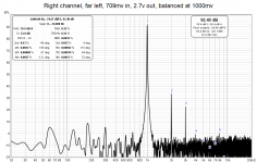
I am using a Focusrite Scarlet connected directly to the signal output from my front end board, feeding into a laptop running Room EQ Wizard. REW provides an FFT display with a distortion panel, showing the percentages and degrees of each distortion harmonic.
I'm feeling lost, as I seem to have more parameters than I can adjust. In order to get low distortion, I have to sacrifice DC offset (minimum distortion is achieved with a DC offset approaching 2V).
What do you use for these adjustments? How do you reconcile the above?
Maybe I should get different color capacitors.... 😛
No mention is made of P1/P2 or the DC offset in these discussions. The only mention of those is that P1 and P2 should be balanced to minimize DC offset.
When I adjust P3, I do observe changes as described. But it completely screws up my P1/P2/DC Offset balance. When I adjust *those* values, it changes the harmonic balance I set with P2. My adjustments of the balance between P1 and P2 seem to set the harmonic balance, without regard for P3. That is, I could set P3 anywhere I wanted, and also achieve whatever distortion profile I wanted. What's the difference between the same distortion profile with P3 at minimum vs. maximum?
I am using a Focusrite Scarlet connected directly to the signal output from my front end board, feeding into a laptop running Room EQ Wizard. REW provides an FFT display with a distortion panel, showing the percentages and degrees of each distortion harmonic.
I'm feeling lost, as I seem to have more parameters than I can adjust. In order to get low distortion, I have to sacrifice DC offset (minimum distortion is achieved with a DC offset approaching 2V).
What do you use for these adjustments? How do you reconcile the above?
Maybe I should get different color capacitors.... 😛
Since I can’t edit my last post…
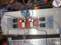
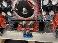
Here’s my latest screwing around. I adopted 6L6’s stacked bias/output board technique, andmounted my Q3 and Q4 transistors on the front panel. I didn’t like them getting in the way, and the legs were weak and I was afraid of them snapping off any time I brushed the heatsink. This approach solves that problem, and reduced temps by more than 10*C! That temperature savings enabled me to increase bias by 50%. Only listed to one album since I got it back together, but so far so sweet!
Here’s my latest screwing around. I adopted 6L6’s stacked bias/output board technique, andmounted my Q3 and Q4 transistors on the front panel. I didn’t like them getting in the way, and the legs were weak and I was afraid of them snapping off any time I brushed the heatsink. This approach solves that problem, and reduced temps by more than 10*C! That temperature savings enabled me to increase bias by 50%. Only listed to one album since I got it back together, but so far so sweet!
Attachments
I also had lower distortion with higher DC Offset until I realized, that the gain was also lower with higher DC Offset.
Yeah, I noticed that too. I tried to keep the output relatively consistent. Can’t there be a knob that just changed *one thing*, not the entire system? 😛
Always adjust for minimum DC offset. There’s no good reason to have “a little” if that’s more than the minimum you can get.
I'm still confused about how to adjust P3. In the BA-3 article, Papa describes turning P3 left and right to adjust the harmonic distortion profile from being H2 dominated or H3 dominated. In 6L6's video with the distortion analyzer, this is what he describes doing.
No mention is made of P1/P2 or the DC offset in these discussions. The only mention of those is that P1 and P2 should be balanced to minimize DC offset.
p
Papas manual does mention this, in as few sentences as Papa needed.
Something like adjusting P3 means you have to revisit P1 and P2. And that revisitation can be a big job. You need to readjust bias and offset almost completely when fiddling with P3. Focus on the distortion profile left when Iq as equal as possible between Q3 and 4, and offset is zeroed. You’ll likely not have the same profile as when you set P3 initially. In other words, either adjust for minimum distortion, or give it time and patience, a lot of it. Or take your amp to 6L6 🙂
yup
everyone needing BA3 setting ( be it pre or full), just send it to 6L6
he'll do that during his lunch pause, while flying on auto-pilot
piece of cake

(more channels you sent, he'll be happier
even more, if it needs repair first)

everyone needing BA3 setting ( be it pre or full), just send it to 6L6
he'll do that during his lunch pause, while flying on auto-pilot
piece of cake
(more channels you sent, he'll be happier
even more, if it needs repair first)
My schedule is pretty quiet for a while, come on by! Setting P3 is easy.
😕 Huh?? 😕
… Add some nice ladies lingerie to the parcel, and success is guaranteed …
😕 Huh?? 😕
Last edited:
My schedule is pretty quiet for a while, come on by! Setting P3 is easy.
😕 Huh?? 😕
A joke from this spring when I tried to figure out how to thank you for saving my WLS build by sending the tiny JFETs I needed that were out of stock, and Mighty gave some good advice 🙂 Maybe misplaced to repeat it here, sorry.
Anyways, it can not be said often enough: what a great guy, and what a great bunch of people this community is!
Always adjust for minimum DC offset. There’s no good reason to have “a little” if that’s more than the minimum you can get.
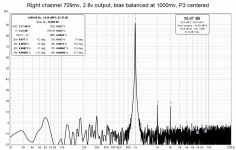
Ok, I'm trying to be scientific now. I took measurements with P3 at far left, far right, and centered, each with the offset minimized. I do see noticeable differences, and I'll try expanding on them.
REW shows a "degrees" field next to each harmonic. Is this worth considering?
Attachments

yup
2nd dominant negative is quite different to 2nd dominant positive
https://www.firstwatt.com/pdf/art_sweet_spot.pdf
https://www.firstwatt.com/pdf/art_h2.pdf
https://www.firstwatt.com/pdf/art_h2_v1.pdf
2nd dominant negative is quite different to 2nd dominant positive
https://www.firstwatt.com/pdf/art_sweet_spot.pdf
https://www.firstwatt.com/pdf/art_h2.pdf
https://www.firstwatt.com/pdf/art_h2_v1.pdf
This one is beautiful... I don't care about the total distortion, as in my experience that makes very little difference, but instead look at the very clean curve (or stair step) of the harmonics decay. Nothing out of place, every higher harmonic lower than the previous.
Wonderful!
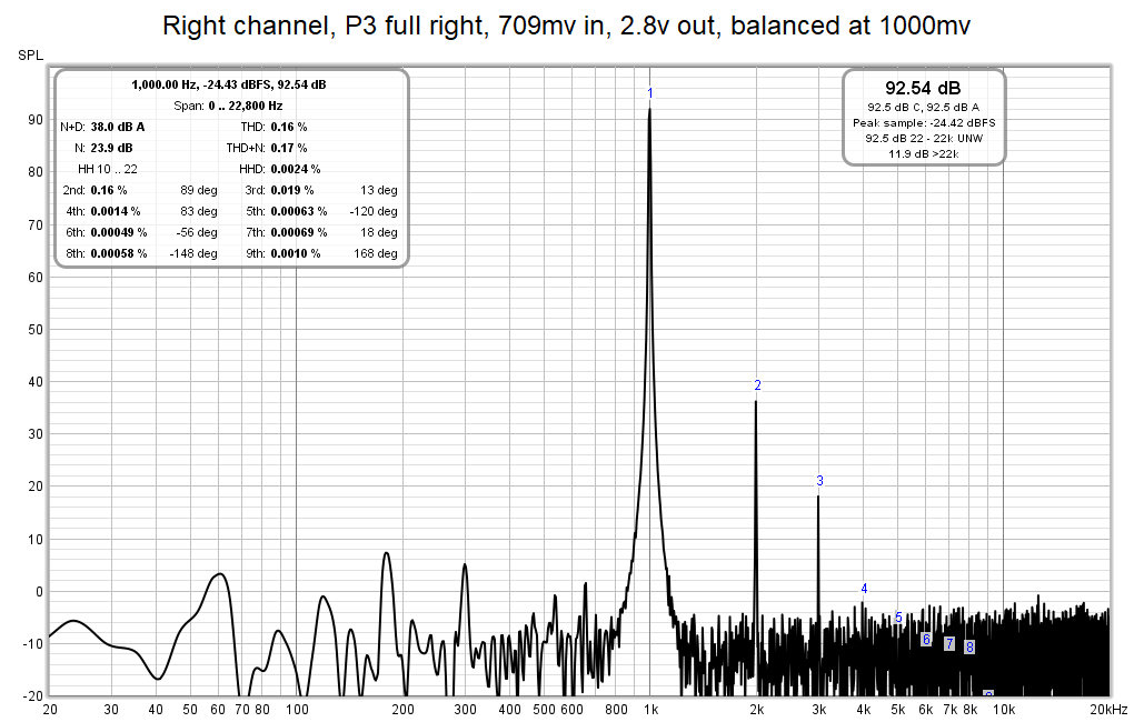
In a perfect world (well, my world, anyway...) I would adjust until the 'step' between H3 and H4 was a little more smooth.. I.E., lower the total H2 if possible, as that will lower H3 as well, and see if the plots could fit on a horizontal asymptote. It's pretty close as-is, so it may just be gilding the Lilly.
But the entire point of P3 is to fiddle around and try stuff, so might as well try.
Wonderful!
In a perfect world (well, my world, anyway...) I would adjust until the 'step' between H3 and H4 was a little more smooth.. I.E., lower the total H2 if possible, as that will lower H3 as well, and see if the plots could fit on a horizontal asymptote. It's pretty close as-is, so it may just be gilding the Lilly.
But the entire point of P3 is to fiddle around and try stuff, so might as well try.
Last edited:
Disclaimer - for general knowledge!
enclosed original pic, by 6L6's sayin' in his contribution in latest BAF, written as it was said in proper English
what is posted in quoted post is pure translation to ZMengrish

(don't fret Jim, lingerie = Zardoz Theme)
enclosed original pic, by 6L6's sayin' in his contribution in latest BAF, written as it was said in proper English
what is posted in quoted post is pure translation to ZMengrish
Attachments
- Home
- Amplifiers
- Pass Labs
- BA-3 Amplifier illustrated build guide