
Does it matter if the output MOSFETS are oriented up or down? Like does one option facilitate better heat dissipation?
Not really. Some people will argue that on the bottom is better, but I’ve tried both and there’s no difference in practice.
At first I mounted them just above the sink vertical centerline. Then I tried the exact positioning that 6L6 used in the guide. At same dissipation, the temp at the top of the sinks was a bit lower using 6L6s way. Relevant? Dunno really. I was in the end most happy mounting them at the lowest point. Wrt them faced up or down (your original question) I would not worry about that (like the master 6L6 suggests).
Last edited:
Was a bit worried the fets would run at higher temp since placed so close to sink bottom. Turned out not to be so, running at happily same temps as the ones mounted higher 
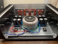
So, this is starting to look like an amp… So many things I wasn’t expecting, so many lessons learned. So much still to do…
I welcome feedback at this stage. Anything that seems like I’m going off in a bad direction, etc. I’m already thinking of moving the power supply boards back a bit.
I welcome feedback at this stage. Anything that seems like I’m going off in a bad direction, etc. I’m already thinking of moving the power supply boards back a bit.
Attachments
to SoaDMGTguy #887
Good morning,
good advice from 6L6. Your build is looking very good to me.
Continue with quality work...😉
Cheers
Dirk
Good morning,
good advice from 6L6. Your build is looking very good to me.
Continue with quality work...😉
Cheers
Dirk
So, this is starting to look like an amp… So many things I wasn’t expecting, so many lessons learned. So much still to do…
I welcome feedback at this stage. Anything that seems like I’m going off in a bad direction, etc. I’m already thinking of moving the power supply boards back a bit.
Looking good. Consider thermal paste under your rectifiers, and torque them appropriately to approx 2Nm, though not critical. I also see you split your PSU boards, perhaps making it more difficult to get a quiet audio gnd. Though, Cubicincher himself has done this and succeded, so you’re probably OK.
Also, although practical for a number of reasons, putting the front end on the front panel has some disadvantages. One of them is long runs of input wire. I would twist them all tight, both channels, and run them together along chassis bottom and not split up until at the front end 🙂
Good luck!
Ie: looking good
Andy
Is running the input wires close to the transformer not a concern? My first idea was to run them along the sides, above the output boards, or possibly straight over the top, taking the shortest possible path. I assume twisting both sets of input wires together reduces possibilities for interference?
You are correct and I was not clear in previous post.
Short as possible=not nescessarily the best solution, you need to keep them away from all the noisy and magnetical parts: rectifiers, tranny and AC wires.
I recommend bottom of chassis, though trying and testing probably the best way to determine what is most quiet.
See hifisonix.com. Bonsai has made a huge PDF/PPT, and an example of signal wiring is there.
In short, twist them together near one of the inputs, then follow outer chassis edges either along top - as you plan - or bottom, keeping in mind where the noisy parts are. And all four wires twisted together. Then you can try one run at either side of chassis, and see if there is a difference.
But check that article, good stuff 🙂
Regards,
Andy
Last edited:
Thanks for the reference!
“ Keep input connectors right next to each other and insulated from the chassis. Bond the signal returns together. Use a single RFI 2-5nF cap to the chassis right at the inputs”
So what he’s suggesting is to connect the L and R input grounds to each other, and connecting that shared connection to the chassis via a 2-5 nF capacitor? I can do that… just want to make sure I understand him correctly.
There it is: http://hifisonix.com/wordpress/wp-content/uploads/2019/02/Ground-Loops.pdf
I was too lazy to link in post. After coffee, less lazy
I was too lazy to link in post. After coffee, less lazy
Thanks for the reference!
“ Keep input connectors right next to each other and insulated from the chassis. Bond the signal returns together. Use a single RFI 2-5nF cap to the chassis right at the inputs”
So what he’s suggesting is to connect the L and R input grounds to each other, and connecting that shared connection to the chassis via a 2-5 nF capacitor? I can do that… just want to make sure I understand him correctly.
I would not sweat that right now. If you have noise issues, and troubleshooting uncovers there is a need for a cap, then do it. For now, I would just keep it simple 🙂
Oooh, looks like I have some reading to do! Thanks so much for the link! I just skimmed the document, looks really clear and helpful. Thanks for the help, friend!
No problem, friend! 🙂 And as always, 6L6s way of wiring in the guide gives nice input also for builds with other layouts. He has A LOT of experience, try and see where he puts wires and what he twists and not.
Good luck! Looking forward to seeing more 🙂
Good luck! Looking forward to seeing more 🙂
I liked his input board placement. The only reason I didn’t copy it is I wasn’t confident on my ability to drill and tap clean, properly spaced holes in the back panel.
- Home
- Amplifiers
- Pass Labs
- BA-3 Amplifier illustrated build guide