Make yourself a template (aluminium, oak etc) that you can clamp down and the hole will come out pretty clean. Take great care not to fall through though (but that’s for the frontplate, haha)!
I should probably get the drill press I've been hemming and hawing about for years. That would simplify things greatly.
A drill press i probably a good idea. Though, for that kind of drilling, unless you care a lot about what is visible under the bolt heads and washers, I’d just go for it 
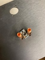
Oh, I'm not worried about that. This is how I attached my non-standard speaker binding posts (not seen is the janky Dremel cut between the two pre-drilled openings). That metal piece is part of the handle of a spring-clamp I cut off 🙄
My main concern is accuracy and straightness, especially when drilling through anything with depth. The last time I drilled through (carefully marked) steel I was still a little crooked, partially due to bit slipping. I'm sure my skills will improve as I continue with this hobby.
EDIT: I'm still working through the grounding and wiring article, but something stuck out to me. He mentions twisting wires together to minimize loop areas, but also suggests that running parallel traces on a PCB would accomplish the same. Would running wires in parallel, but tightly bound together with ties, accomplish the same thing? So far I have not read about any special effect the twisting provides.
Attachments
Last edited:
I find aluminum much easier to work with and if you use a drill press you shouldn't
have any problem.
I also use the pcb as a drilling template. I drill and tap one hole, and then
tighten the pcb on the metal and go on to another hole. Then repeat the process
until I'm done.
have any problem.
I also use the pcb as a drilling template. I drill and tap one hole, and then
tighten the pcb on the metal and go on to another hole. Then repeat the process
until I'm done.
I believe it is something about the rotation of the contacting/touching part of the wire, which enhances cancellation (or makes it happen at all)
It's the two wires crossing each other at (close to) 90 degrees (repeatedly) that helps with noise cancellation.
Have a look at Audio Notes amplifiers. Low feedback toobz, hand built, and often point to point wiring. Most wires are twisted the heel out of, like having to use a drill to achieve those angles.
And then, look at Papas builds. Twisted, but not more than keeping things close and relatively tight.
How much should you twist? You could play it safe, and «overdo» it right away, or just copy 6L6 and Papas twisting. some people hardly twist at all, and it still works smooth.
IME, the BA-3 likes things twisted good, lowers noise also in upper freqs. But then I see others having it quiet from the get-go without any fuss. I gues the advice is: try and listen, and modify if needed 🙂
Noise or hum that a person hears at their speaker is relative to speaker sensitivity.
An amp or preamp with sloppy wiring/poor component placement/poor control of EMF may seem quiet with 85dB speakers but sound really noisy with 100dB speakers.
So any claims to system noise should include speaker sensitivity.
In my builds, I try to achieve the lowest noise that I can. Then I don't have to trouble shoot later. But then my speakers are very sensitive. However, even if you don't have sensitive speakers, I think the best approach is to do the best that you can. Then your amp or preamp can work with sensitive speakers if you change speakers.
I definitely twist wires and try to minimize loop areas. My favorite resource by diyAudio member Bonsai:
http://hifisonix.com/wordpress/wp-content/uploads/2019/02/Ground-Loops.pdf
Andy, I see that you have already posted the link in post #895.
Last edited:
Thought about it then forgot: I suggest you also do a forum search for Bens builds. He is a notorious hum and noise chaser, top notch, along with many other good things - including being a great person. Follow his advice, and you’ll be hard pressed to have noise issues 

In many years building audio stuff, noise and hum have always been my fear, I've met failures...
Currently my BA3 (with a 2018 Linestage) is connected to a high efficiency speakers, fortunately I don't hear any noise/hum, as well as the ALEPH J previously built, I'm really grateful to papa and this community.
Currently my BA3 (with a 2018 Linestage) is connected to a high efficiency speakers, fortunately I don't hear any noise/hum, as well as the ALEPH J previously built, I'm really grateful to papa and this community.
Is it reasonable to rely on the anodized film on panels to insulate them from plugs/etc, or should I take special precautions do maintain isolation?
If I touch my multimeter leads to the black anodized surface of my back panel, I don't get continuity to other points on the panel. If I put an uninsulated plug through that panel, I do not get continuity between the plug and the panel (example: BA-3 Amplifier illustrated build guide) (Yes, I see the exposed spots from my shitty Dremel work, I'm going to cover those)
Should I add some sort of insulating ring between those copper posts and the black anodized surface of the panel? Even if the anodization is insulating now, could it get scratched off during normal use?
Should I add some sort of insulating ring between those copper posts and the black anodized surface of the panel? Even if the anodization is insulating now, could it get scratched off during normal use?
Thanks, will do. While we’re on the subject, are screw connections sufficient to ground panels to each other? IE, if panel A is screwed to bracket B which is screwed to panel C, and I have continuity from a screw in panel A to a screw in panel C, can I connect a screw in panel A to ground and consider all panels grounded, even if the panel face to pane face connection is not conductive?
(I assume the answer is yes)
(I assume the answer is yes)
It depends on the finish on your panels. If the panels are bare metal then there should be continuity.
If your panels are painted or anodized, then there may not be continuity. Although anodization should not be counted on for electrical isolation/insulation when it is required, it can prevent electrical conduction. So it is best to check for continuity between panels. When in doubt, sand the panels at one screw location minimum per joint to ensure continuity between panels.
If your panels are painted or anodized, then there may not be continuity. Although anodization should not be counted on for electrical isolation/insulation when it is required, it can prevent electrical conduction. So it is best to check for continuity between panels. When in doubt, sand the panels at one screw location minimum per joint to ensure continuity between panels.
- Home
- Amplifiers
- Pass Labs
- BA-3 Amplifier illustrated build guide