I'm having trouble measuring the adjustments I make to P3. I can absolutely hear differences as I blindly turn the pot while music is playing. But I'm having trouble quantifying those changes when examining the harmonic products.
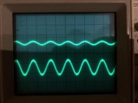
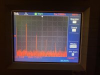
Attached is what I see when I run 1w into a resistor (2.65v into 7ohms). My source signal is "1 KHz" (9.66 because I need to calibrate my generator). I observe harmonics at nicely decreasing magnitude at ~2 KHz, 3 KHz, 4 KHz, and 5 KHz.
When I adjust the P3 pot from minimum to maximum values, the magnitude of the 2nd and 3rd harmonic barely change. The 2nd is always ~7 dB higher than the 3rd. (and about 20 dB down from the primary signal) At most they might vary up and down by ~ 2dB together, and at most they might vary between each other by 1 dB.
I don't think it's a resolution issue, as each harmonic is clearly delineated above the noise floor. I'm doing this with one channel driven, but I didn't think that should make a difference.
Attachments
Hi!
You probably should be careful adjusting while playing. Adjusting P3, changes current through the JFETs, affecting the MOSFETs current in turn, measurable with one DMM at each of the 22R resistors. These changes can be significant. I would recommend you rebias/adjust offset after each P3 adjustment, and then take your measurements.
That said, I have never succeeded in adjusting P3 the pro way, as my old HP distortion analyzer turned out to need recap and a service. Needless to say, that is still pending.
Please wait for others to chime in, but as far as I am concerned, and referring to the manual by Papa: adjust P3, readjust P1 and P2, then you’ll know what you have.
Edit: due to C3, there is no danger to the OS, like on the F5T. Possible danger if one of your FE MOSFETs pop. But that pop will be smaller than one on the OS. Just saying.
Regards,
Andy
Last edited:
P3 is 100R?
btw. while fiddling with P3, you need to observe both output node (inside end of C3) voltage and current through Q3,Q4 ...... and counteract with P1 and P2 to get them to prescribe settings
who sez that Papa's simple amps are simple to set?

btw. while fiddling with P3, you need to observe both output node (inside end of C3) voltage and current through Q3,Q4 ...... and counteract with P1 and P2 to get them to prescribe settings
who sez that Papa's simple amps are simple to set?
Sorry, forgot the offset measurement at C3 vs audio gnd. That is one fiddly adjustment! Best not heat your house a degree or two, it will change. Sometimes significantly. Though it sounds lovely anyways. C3 saves the day.
P3 is 100R?
btw. while fiddling with P3, you need to observe both output node (inside end of C3) voltage and current through Q3,Q4 ...... and counteract with P1 and P2 to get them to prescribe settings
who sez that Papa's simple amps are simple to set?
It’s an exotic creature, aren’t all exotic things a bit fiddly? Luckily, the BA-3 sounds a lot better than this cat looks:
Exotic Shorthair
Ahh, ok. I will do that and try again. I get impatient🙄
Yes, P3 is 100R.
ZM, are you saying basically that I need to recheck bias and offset after each adjustment? I didn't recognize the procedure as you framed it, but I think that's what you're saying?
The pot I got doesn't seem to have any physical indication for when it's reached an end 😕 Measuring between pin 1 and pin 3 while mounted to the board with power off I get a range of 9.7 ohms to 17.7 ohms. I can keep turning past these points, but the values stop changing. Do I need to do something else to get a valid range? If I have to pull them to check, how can I mark my boundaries so I can set accurately once it's reinstalled?
This is the part I got: 67WR100LFTB BI Technologies / TT Electronics | Mouser
I don't care if it changes once I've set it, as long as it changes relatively to my adjustments!
yes, each fiddle with P3 demands re-check and (if needed) re-set of DC level of output node and mosfets Iq
that's multiturn pot, it doesn't have stops you can feel, maybe just hear tiny click
if it is 100R, don't bother to check it - in circuit it is practically in parallel with JFet source resistors
that's multiturn pot, it doesn't have stops you can feel, maybe just hear tiny click
if it is 100R, don't bother to check it - in circuit it is practically in parallel with JFet source resistors
I’m going to need more multimeters!
Is there a way I can identify relative position of the pot without having to remember how many turns I’ve done in each direction?
Is there a way I can identify relative position of the pot without having to remember how many turns I’ve done in each direction?
third eye?

that's why you have scope and analyzers , to see are things changing or not
counting turns and memory ............ not overly trusty techniques
that's why you have scope and analyzers , to see are things changing or not
counting turns and memory ............ not overly trusty techniques
I’m going to need more multimeters!
Is there a way I can identify relative position of the pot without having to remember how many turns I’ve done in each direction?
Whilst waiting to fill your workshop with all equip needed, you could put two DMMs across R3+4 (the 10R resistors before the JFETs), and ensure equal voltage drop across them. This might not be the exact middle point, but will at least ensure equal current sharing between JFETs. A possible starting point. I did that, and at least the two channels sounded the same wrt harmonics, though they probably weren’t 🙂 With standard store BL JFETs you should get between 50-65mV drops, with 10mA ones approx 80mV. This one is quite easy to adjust. JFETs in this circuit being more stable than gremlin MOSFETs.
Remember to readjust P1-2 (bias and offset) aftwerwards. Also monitoring so you don’t blow anything in the P3 adjustment process.
Again, not a very trustworthy method, but good enough for muzak.
I’m going to need more multimeters!
Is there a way I can identify relative position of the pot without having to remember how many turns I’ve done in each direction?
Measuring between Pin 1+3 of the pot, as you did, should tell you the position of pot. Maximum of 16R7 (+contact resistance if measured in 2point) should be midway and Minimum of 9R1 should be either extreme.
Do you measure whole amps output or only the front end? Try measuring only the front end. The OS will overwhelm the FE.
Yes Offset+Bias change with each P3 turn.
At least my Oscilloscope (TEK TDS 724A) sucks at THD measurements being 8 bit and all. I much prefer soundcard with ARTA or my Keithley 2015 THD multimeter.
You will work this out for sure

I'm getting there... slowly... full thanks to you guys 🙂 <3
I'm getting clear harmonic frequencies at easily measurable levels. Is the low-resolution of my scope still causing an issue? I was expecting changes with regard to the levels of the 2nd and 3rd harmonic, and I would be able to tell easily which one was dominant at 1W output. Unless there's something I don't understand about FFT resolution?
At least my Oscilloscope sucks at THD measurements being 8 bit and all.
I'm getting clear harmonic frequencies at easily measurable levels. Is the low-resolution of my scope still causing an issue? I was expecting changes with regard to the levels of the 2nd and 3rd harmonic, and I would be able to tell easily which one was dominant at 1W output. Unless there's something I don't understand about FFT resolution?
Without a notch filter a 8 bit oscilloscope can meaure up to the 1/256 th part of maximum input. This translates to 0,39% distortion. Your BA-3 is better than that.
If you have a 16 bit scope or soundcard you can measure 0.0015% THD and so on. With a notch filter you can knock the fundamental down say a 1000 times or more and then your 8 bit oscilloscope measuring the much lower signal (knocked down fundamental + harmonics) can resolve properly. You then have to calculate how much the notch filter filtered the fundamental and most of the times also some of the harmonics.
So you can use a notch filter and adjust for minimum and give a damn about calculation. Or you can use a cheap soundcard without a notch filter or a proper function analyser with built in notch filter. With a low distortion source signal, I found the Keithley 2015 to be as precise as my soundcard - so thats what I use for convenience.
front end is having so much active parts, so it's ludicrous even to think of pulling them all and test .........
and you'll learn how to test mosfets and JFets
and you'll learn how to test mosfets and JFets
Ahh, I see you saw my now-deleted post. TL;DR: I had managed to get P1 and P2 so far out of alignment I couldn't see the results of turning them. That, combined with me not thinking clearly because "ZOMG 25 VOLTS?!?!?!?" led me to not see the solution, which was simply to adjust P1 and P2 until the bias voltage across R11 and R10 was normal, at which point the voltage across R13 was back down to a couple hundred millivolts.
All is again well. I apologize for needlessly summoning you 🙂
All is again well. I apologize for needlessly summoning you 🙂
Yepp full rail DC on output smells like a shot transistor. You can easily test this. Start with the output mosfets.
How to Know if MOSFET is Defective | ElectronicsBeliever
We all started out as dumbasses and some happily stay that way 😀
How to Know if MOSFET is Defective | ElectronicsBeliever
We all started out as dumbasses and some happily stay that way 😀
I will never stop being a dumbass. It’s the greatest thing ever, constantly improving with little or no effort
- Home
- Amplifiers
- Pass Labs
- BA-3 Amplifier illustrated build guide