read randomly
when tired, look at pics of FW amps
there are links for each product review
who needs forums, when everything is at hand's reach?

when tired, look at pics of FW amps
there are links for each product review
who needs forums, when everything is at hand's reach?
Also, I heard about some guy in Europe, doing some crazy stuff. You should check out that too: Zen Mod Blog – Buddha is everywhere…….
MZM: of course one needs forums. What is read can be misread, and who would be there to help us GH’s?
MZM: of course one needs forums. What is read can be misread, and who would be there to help us GH’s?


Ohh no - all this talking about Harris devices got me thinking, how they might sound like.
So as audio nervosa crept in, I found that Rochester is still selling them and I order 100 pieces:
Rochester
or via Digikey
I will do some measurements as well on how they compare balanced/single ended.

So as audio nervosa crept in, I found that Rochester is still selling them and I order 100 pieces:
Rochester
or via Digikey
I will do some measurements as well on how they compare balanced/single ended.
Haha! I love it. Good luck, Ozor!
PS: if you have any spares after matching up the ones you need yourself, consider me interested 😀
PS: if you have any spares after matching up the ones you need yourself, consider me interested 😀
😀
For sure Andynor - I will post here in a couple of weeks how it went and how many are left over.
For sure Andynor - I will post here in a couple of weeks how it went and how many are left over.
Trying to find a cure for the "audio nervosa" illness I ran across this post, which made me laugh audio nervosa
have a good one everybody
have a good one everybody
Trying to find a cure for the "audio nervosa" illness I ran across this post, which made me laugh audio nervosa
have a good one everybody
You could insert a dial to everything. It should basically give you haptic and visual feedback (like, dim a led) but not touch the circuits. It could me made so that some sort of equilibrium between them could be achieved (much like biasing ba-3 pre). If you feel AN, touch one of them.


I have never matched a MOSFET in my F5 or BA-3 FE and never saw any instructions to do that in the guides.
F5 v1 and BA-3 Fe have no parallel output devices, so no matching required besides the JFETs.
The more output devices and the lower the source resistors the better the match needs to be so output current is equally shared.
That being said the 100 pieces from the same batch that I measured were really close. My chances would have been 5% or so to get a really bad match and hence start blowing devices.
But as Papa says it is easy to do and if it makes the amp safer and better why not do it. One can always sell, gift or keep left overs as spares for a lifetime supply.
Is your BA-3 still in the making?
Whats missing? or is it just time - I´d say one week should be sufficient.
People get much older than they used to and when on pension, one has more time to build or blow output stages.
Whats missing? or is it just time - I´d say one week should be sufficient.
People get much older than they used to and when on pension, one has more time to build or blow output stages.
BA-3 iteration 1 is finished, but now dismantled iot redo it all and put J Zen in instead. I am slow due to family situation. Once building I have gotten pretty fast.
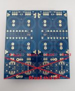
I'm really struggling to understand how to build the rectifiers and filters in the diyA Universal PSU design. My inclination is to build the First Watt Power Supply on the Universal PCB and use monolithic rectifiers. As far as I can tell, this shouldn't be a problem, right?
Yep should be easy peasy. Screw rectifier to heatsink (often case). Connect transformer secondary to rectifier (marked with a sine symbol or so). Connect + (usually marked + or pin little different or edge chamfered) and - from rectifier to capacitor PCB. Take care to solder the capacitors minus pole to the minus side (white bar on the pcb cap symbol).
Attachments
If using that PCB, IMO, you should EITHER get hold of soft recovery diodes - ie not in the BOM, which can be expensive, or use - as you suggest, monolithic bridges.
If using monolithic bridges, you need to snap off/break apart the diode section from the PCB. No biggie. In a cold room, just snap it off. Than road is clear for using monolithic bridges.
So:
1: Transformer
2: 2 x bridges (standard Vishay 35A is fine)
3: Universal PSU PCB but without the diode (front) section.
Remember, solder when possible, omit snapons/blades if you dare. Euroblocks are also not the best solution, but very very practical.
If I were you? I would ask Zen Mod if he has some spare PSU PCBs for you, in exchanfe for mighty amount of greenies.
Regards,
Andy
Andy’s advice!
ZenMods boards are very cool.
Else, the f4 build guide by 6L6 is pretty useful here… A guide to building the Pass F4 amplifier.
(For the Cap-bank, see diyAudio Power Supply Circuit Board v3 illustrated build guide)
ZenMods boards are very cool.
Else, the f4 build guide by 6L6 is pretty useful here… A guide to building the Pass F4 amplifier.
(For the Cap-bank, see diyAudio Power Supply Circuit Board v3 illustrated build guide)
They are especially cool in that they are not so universal, rather optimized for FW and such amps (bipolar). The ground plane tracing is especially cool. Pictured myself the perfect way, then I saw my thoughts in that PCB, but of course better than what I had imagined
A worthy addition the store, IMHO.
Regards,
Andy
A worthy addition the store, IMHO.
Regards,
Andy
- Home
- Amplifiers
- Pass Labs
- BA-3 Amplifier illustrated build guide