Seems the only time to use P3 to adjust offset, is in case of unmatched or insufficiently matched JFETs. But how to know? The store ones from Linear are matched and the spurce is NP, right?
Andy
Andy
I would not consider that the main use. P3 can be used to adjust the
distortion profile. See for example this video by 6L6:
Adjusting P3, Nelson Pass Burning Amplifier BA-3 - YouTube
Here's a thread you might find interesting:
P3 Adjustment for the average Hobbyist
distortion profile. See for example this video by 6L6:
Adjusting P3, Nelson Pass Burning Amplifier BA-3 - YouTube
Here's a thread you might find interesting:
P3 Adjustment for the average Hobbyist
Last edited:
Seems the only time to use P3 to adjust offset, is in case of unmatched or insufficiently matched JFETs. But how to know? The store ones from Linear are matched and the spurce is NP, right?
Andy
do not do that
P3 is not for offset
period
punkt
dot
!
Dennis is correct, P3 is NOT used to adjust offset.
It is used, with measurement tools, to adjust distortion spectra.
It is used, with measurement tools, to adjust distortion spectra.
Dennis is correct, P3 is NOT used to adjust offset.
It is used, with measurement tools, to adjust distortion spectra.
That had been my understanding as well. But when Nelson in the article writes that P3 can be used if JFETs are not well matched, what does it «fix» in those cases?
that's of secondary importance, and it really depends of your approach/intention
if main goal is absolute symmetry, in other words minimum THD, its somewhat different than usually desired 2nd harm. dominant
but in all cases offset is taken care of efficiently with drain trimpots, while P3 is dealing with effective gain of lower/upper halves of stage,thus shaping THD in direction you're choosing
I would not consider that the main use. P3 can be used to adjust the
distortion profile. See for example this video by 6L6:
Adjusting P3, Nelson Pass Burning Amplifier BA-3 - YouTube
Here's a thread you might find interesting:
P3 Adjustment for the average Hobbyist
I need to go back to the "P3 for hobbiest" thread for update, thanks for the bump.
Russellc
So I was prepared for a burning amp. But I might have taken it a little bit too literally. My BA-3 FE kinda caught fire last night. Everything was dandy, until I was to do a last adjustment of the FE DC offset and bias after cooking for a while.
I managed to short R10 with my probe. Result was that both R10 and R11 caught fire. My sinks are not conductive, but a burnt bolt seems to prove quite a bit of voltage went that way.
Temporary BDA: Burnt R10 and 11, burnt bolt and heatsink (superficial), and a small burn mark on the PCB under R11, thought not hitting any traces.
Am I a fool hoping that replacing the resistors might do the trick? I am prepared for everything, and a new board on the way and parts allready in the basket.
There are no other visual indications of damage to either parts or board. But of course, closer inspection is nescessary. Will post pic later.
Regards,
Andreas
Only one way to proceed, replacing the resistors...that will have to happen in any event if they cooked.
Then the hunt for collateral damage. I managed to kill the FE smaller outputs by a power supply wiring slip up. No smoke no stink, just dead on one side.
Time for variac or dimbulb start up.
Russellc
Then the hunt for collateral damage. I managed to kill the FE smaller outputs by a power supply wiring slip up. No smoke no stink, just dead on one side.
Time for variac or dimbulb start up.
Russellc
Didnt happen on start up, happened cause the alligator clips slipped off 🙁 But thanks, really. Will build the tester, but that was not the prpblem in this case 🙁
So sorry to hear that!!!! It is tight in there. Sorry to provide suggestions after-the-fact, but I think these types of probes are fantastic. I highly recommend getting a few sets. I can't find a link to the exact ones I got, but here's an example.
https://www.amazon.com/HiLetgo-3Pai...=mini+grabber+probe+dmm&qid=1605489451&sr=8-2
https://www.amazon.com/HiLetgo-3Pai...=mini+grabber+probe+dmm&qid=1605489451&sr=8-2
Oh I didn't think so, I just meant if you were afraid something else was damaged in the accident.
So did you get any flames?
Russellc
So did you get any flames?
Russellc
Ah, I see. That is a very good idea, Russel! Yup, flames, a real burning amp. R10 and R11 up in flames. Put it out by blowing on them though. Will check those probes right now!
Hello Andy,
I also use those testclamps that ItsAllInMyHead suggested in his post #492.
The distance from the resistorlegs (R10/R11) to the small heatsinks of the MosFets is very close! 😱
What a pitty! I feel with you 🙄
Don't give up!!!! Looks like you are walking through the 'valley of pain'?
Greets
Dirk
Perhaps time for a beer or a wine?
Wow. Now I'm jealous. I've yet to get flames, I got some good glowing tidbits and lots of smoke, but no flames yet.
Russellc
Russellc
One thing about those little J hook clippers, Once while using them, something shorted and the quick rise in heat caused the metal contacts to melt right through the plastic!
Since then, I try to leave enough resistor lead to get an alligator clip on.
Russellc
Since then, I try to leave enough resistor lead to get an alligator clip on.
Russellc
Thanks guys, your words are both helpful and comforting, but most importantly: motivating.
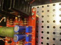
Here are som pics of the finished amp, and the burnt front end. Damage is on the right channel.
Well, was not vompletely finished, as one of the N-channel output board MOSFETs turned out to be poorly matched. So will be changing all three. Also, one of the bias boards did not turn out very well, so will be making a new one. One step forward, three back. Better get used to it.
Overlook pic: I will be swapping the big riser panel for a smaller one fitti g perfectly above the PSU.
Detail pic: Lovely burning amp military spec resistors R10 and 11!
Other pic is right output board. Nothing fancy but I share anyways.
Last edited:
- Home
- Amplifiers
- Pass Labs
- BA-3 Amplifier illustrated build guide