with 6-deep, you have 6 vertical pairs
as per article:
...........each conducting 250mA (Iq) , so sum Iq is 6 x 250mA
rails are 25V
so you have dissipation per channel as (6 x 0A25) x (2 x 25V)= 75W
now, my bet is that there Pa made a typo, so quote from article :
can be used as reference; just double "250mV across 1R source resistor" figure and you're good
with Iq of 3A and 25Vdc rails, The World is your Oyster ........ 🙂
as per article:
The amplifier prototype I built biased the output stage at 250 mA
per output device, which measures as 250 mV across each of
the 1 ohm Source resistors on the output stage. You will want to
gently adjust P101 to this figure while watching the voltage across
one of the 1 ohm resistors. When you reach that figure, use the
multimeter to confirm a close value across all the 1 ohm output
stage resistors.
...........each conducting 250mA (Iq) , so sum Iq is 6 x 250mA
rails are 25V
so you have dissipation per channel as (6 x 0A25) x (2 x 25V)= 75W
now, my bet is that there Pa made a typo, so quote from article :
The power transformer should be rated at 600 VA or more. Two
channels of this amp will may draw as much as 300 watts, and we
allow at least a 2 to 1 transformer margin.
can be used as reference; just double "250mV across 1R source resistor" figure and you're good
with Iq of 3A and 25Vdc rails, The World is your Oyster ........ 🙂
As follows: 2x24v secondaries. 32v rails, 30v under load. 0,47ohm source resistors.
I will get 0,5 amps with 0,235v drop across source resistors. With 32v this gives 16 watts per device (6L6 way of finding watts in this guides 1st page). Maybe go a little higher since rails under load are 30 and not 32v?
Using your way of finding dissipation, 0,5amps with 32vdc rails puts dissipation at 192w per side, exceeding half the transformers (600va) capacity. So is 0,39 amps per device and 2,34amps per side my max here? If so, 0,183w across source resistors is my target. I have biased at 0,185 furing testing, but to be honest, not much heat developed. More confortable than hot to the touch.
What would be safe wrt amps and dissipation in this case?
I notice 6L6 in this guide uses amps*rail voltage=watts.
Whilst you multiply rail voltage by 2 to get dissipation, the way I have always done it figuring out mains watts and so on.
Am I missing something? Maybe I should take som math and physics classes =D
Last edited:
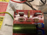
In the aftermath of the resistor-fire, I have finally managed to spend a little time cleaning up the mess. It turned out better than expected. All the burnt stuff came off, turned out to be only soot, and pads came out OK after desoldering. Ready for new resistors.
All sourrounding 100 ohm resistors measure OK. P1 and P2 also undamaged. But the MOSFETs? Should be interesting =)
All sourrounding 100 ohm resistors measure OK. P1 and P2 also undamaged. But the MOSFETs? Should be interesting =)
Attachments
Last edited:
1: Applying the same math to the front end, means that with 32v rails, the real bias of 1: Q3-4 becomes higher than the original. The question is then: do I aim for the original dissipation of ca 1,125 watts, meaning 0,773v across R10 and 11, or let it rip and go for 1v, ending up with 1,44 watts on Q3 and 4. what is the wise thing to do, for starters? Some have reported that it is more difficult to zero offset at higher bias points. The question I ask myself then, is if part og the explanation had to do with people - like me - having more than 25v on the rails, and effectively biasing higher than the original circuit when aiming for 1v across R10 and 11?
2: For both the FE and the outputs: Do I adjust bias according to unloaded rail voltage, with is 32v, or rail voltage under load which is only 30 volts?
Forgive all the questions, please. I really want to understand =)
2: For both the FE and the outputs: Do I adjust bias according to unloaded rail voltage, with is 32v, or rail voltage under load which is only 30 volts?
Forgive all the questions, please. I really want to understand =)
1. I wouldn't use input JFets without cascodes at 30-32Vdc rails; that's begging for trouble ..... and if not - I would be extremely uneasy, and what's the point listening da musac when feeling uneasy
-T0220 Mosfets - just take care that they're adequately heatsinked and keep same Iq as Papa prescribed with original (25Vdc rails)
2.how you are going to calculate dissipation of channel - that's irrelevant, as long you get same number of W in all calculations ; I'm always taking Iq per vertical pair, then multiply with number of vertical pairs, then multiply with sum of rails; you can calc as Iq per mosfet, then multiply with sum number of all mosfets then multiply with value of one rail
why I'm using "my" way - simple per habit - I'm used to see amp as concept, where I see just one pair of outputs as necessary for function, thus everything bigger to me is just multiplying basic amp (concept) ........
now, in your case - you can go backwards:
- take in account how much watts your heatsinks can get rid off;
- take in account how much watts of heat per one mosfet you can cope with
whatever of these two you reach first, stop there
me- I wouldn't use more than 30W of dissipation per mosfet in your 3-deep configuration; taking in account loaded rail value ( that's effectively rail value while amp is functioning; who care what's 0-100km/h hour of your car, while car being on car lift?)... so , no more than 1A per mosfet, which is 0V47 across your 0R47 source resistor
cascoding of input JFets - same as with F5T;
and - do not bawl - only you are responsible for decision of using that rail voltage and using 3-deep instead of 6-deep ........ so now you must do both cascoding and must ask questions, instead of following already shown
Andynor, please also note that with higher rails you'll have to increase
the total bias to the output stage if you want to keep it fully in class A.
Same considerations/limitations on dissipation/temp per mosfet and
heatsink apply.
the total bias to the output stage if you want to keep it fully in class A.
Same considerations/limitations on dissipation/temp per mosfet and
heatsink apply.
Thanks, guys!
I know I SHOULD cascode. But I want to avoid it. I will rather get a new transformer with lower voltage secondaries, to be honest, the reason I use 32v rails? I had two transformers on hand, both 2x24v secondaries. So I want to use them instead of buying a new one, if I can. Furthermore, 6L6 used 2x24v secondaries in the build guide. So I thought: let’s give it a shot.
I am daily contemplating buying a Toroidy of fitting voltages. But I have concluded it is better to get the amp actually functioning, and then consider changing the transformer.
Why the BA-3? Let’s just say I got the boards as a gift, and whilst I was planning to build a F5T, I in the end decided not to do so for my first project. It is on the list, however.
What would you do in my situation? Simply swap transformer?
Is it really that big a risk putting the JFETs through 30 volts day in and day out? 6L6 and Russel: Yours still work, right?
Looks like I am in the market for a new transformer...
if you don't need power, which you're getting with higher rails, then better to use lower rails - lesser heat, lesser AC bill ( if you care), lesser stress on tiny input JFets 
if you need...... that's another story
cascoding - I'm Sissy, not member of ABFAB 🙂
if you need...... that's another story
cascoding - I'm Sissy, not member of ABFAB 🙂
Haha! I love it. I am, apparently, a member. But that was not intentional. Referring to my amp fire the other day. Jeeeeez...
Being predicative of the worst that could happen, is not being a sissy, Zen. It is being smart! Remember, too much brain can be a bad thing too. Best use it when possible!
Being predicative of the worst that could happen, is not being a sissy, Zen. It is being smart! Remember, too much brain can be a bad thing too. Best use it when possible!
if you don't need power, which you're getting with higher rails, then better to use lower rails - lesser heat, lesser AC bill ( if you care), lesser stress on tiny input JFets
if you need...... that's another story
cascoding - I'm Sissy, not member of ABFAB 🙂
Don’t nescessarily need that much power per se, but I ned current for my Fyne F502s. Which btw are currently connected to a Nuprime with class D output stage. It is not an experience that promotes long sessions...
Last edited:
in that case (Fyne, ZM having extrashort short memory ) , keep existing xformers and cascode JFets
) , keep existing xformers and cascode JFetsShort memory, haha.
So 30 watts per MOSFET. Is that not the double of what my transformer can handle? Given 1:2 ratio, and 600va transformer, I can either bias to 12,5 watts per device, or 25 watts per device. It comes down to whether i multiply rail voltage by 2 or not.
I was aiming for 12,5 as max. Are tou saying I can safely go to 25 with a 600va transformer? Given sinks are big enough of course.
now you're really typing faster than thinking
dissipation per channel is easy calc, you can't randomly multiplying rails voltages
it's up to you how much, taking in account heatsinking capability and PSU capability
600VA xformer , if of good quality, will cope well with 300W consuption
when I said 30W of dissipation per mosfet, I meant it as max value I'll go for, when using 3-deep , considering their mounting in group etc.
when used solo - example - my Babelfish J , using just one pair of IRFP150 - well cooled - up to 50W per mosfet
Well, the amp works. Good news after the fire incident. Currently doing music duty, but not pushing it yet. But affirmed it actually works and plays music.
But, there is some hum from the 91db speakers. Both channels, volume independent. I am pushing the transformer, I know, with 0,5 amps bias. I can actually hear the transformer putting my ear to the chassis. The loudness of the hum from the speakers sound just like the hum from the transformer, frequency wise. It is not loud, but O can hear it from the listening position if the sorroundings are quiet. So possible to live with, but not good enough for me.
But does that mean the sound should end up in both speakers? Are we talking wiring faults, or magnetic coupling? Or just a very loud transformer?
Will try to reduce bias and see if anything changes. To be honest, I did not have much hope for this transformer, Noratel 600va 2x24v secondaries. But, I had not expected hum from the speakers.
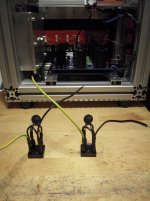
You can see my wiring from pics in earlier posts. However, no pics of the wiring at the back of the PSU. Will try to post some pics of that tomorrow.
In the meantime: any tips as to how to identify the reason why the hum ends up in my speakers?
Cheers,
Andreas
But, there is some hum from the 91db speakers. Both channels, volume independent. I am pushing the transformer, I know, with 0,5 amps bias. I can actually hear the transformer putting my ear to the chassis. The loudness of the hum from the speakers sound just like the hum from the transformer, frequency wise. It is not loud, but O can hear it from the listening position if the sorroundings are quiet. So possible to live with, but not good enough for me.
But does that mean the sound should end up in both speakers? Are we talking wiring faults, or magnetic coupling? Or just a very loud transformer?
Will try to reduce bias and see if anything changes. To be honest, I did not have much hope for this transformer, Noratel 600va 2x24v secondaries. But, I had not expected hum from the speakers.
You can see my wiring from pics in earlier posts. However, no pics of the wiring at the back of the PSU. Will try to post some pics of that tomorrow.
In the meantime: any tips as to how to identify the reason why the hum ends up in my speakers?
Cheers,
Andreas
Last edited:
Hello Andreas,
fantastic news! Enjoy the sound!

The hum could also be caused by your ground routing - not only by the transformer.
Seems to be 50/60 Hz - hum from mains - how you describe it.
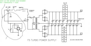
Have you built an ground-loop-breaker between audio-ground and mains-ground?
Nelson Pass uses often a 35A - rectifier - bridge together with a CL60- thermistor to do this.
I have to search for the pic / schematic. It is easy.
I used it.
Greets
Dirk
fantastic news! Enjoy the sound!
The hum could also be caused by your ground routing - not only by the transformer.
Seems to be 50/60 Hz - hum from mains - how you describe it.
Have you built an ground-loop-breaker between audio-ground and mains-ground?
Nelson Pass uses often a 35A - rectifier - bridge together with a CL60- thermistor to do this.
I have to search for the pic / schematic. It is easy.
I used it.
Greets
Dirk
Mechanical noise from the transformer and hum at the speaker tend to have
different causes.
First try shorting the inputs of the amp and see if the hum at the speakers go away.
If so, that's indicative of a ground loop.
DC on your mains power can cause transformers to hum.
different causes.
First try shorting the inputs of the amp and see if the hum at the speakers go away.
If so, that's indicative of a ground loop.
DC on your mains power can cause transformers to hum.
Hi. Dirk and Dennis! Thanks a lot for your input.
I actually had planned to try shorting the inputs. So thats probably the first thing I will do, it is the easiest.
Dirk: I have the ground loop breaker iaw schematic. Basically thought I did everything right 🙁 Btw. The frequency I assess to round about 100 hz, not as low as 50. Sounds just the same as when putting my ear close to the transformer.
Dennis: Even if there is DC on the mains, causing the transformer to hum, it should not appear at the speakers either way. Hmmm. This was an irritating one.
Plan:
1: Short inputs and check for changes.
2: Reduce bias and check for changes
3: Check orher wiring, perhaps this one first of all =)
Come to think of it, I have had ground loop issues in the past. But they were always volume dependent, as opposed to now.
Last edited:
- Home
- Amplifiers
- Pass Labs
- BA-3 Amplifier illustrated build guide