....... with 0,5 amps bias. .....
now, I'm confused
you said - 3 deep
taking in account that you probably meant 0,5 amps is per one vertical pair (1V across 0R47 source resistor), that means sum Iq per channel is 1A5
rails are 30V-ish
so, dissipation per channel is 1A5 x (30+30)V = 90W
??
now, I'm confused
you said - 3 deep
taking in account that you probably meant 0,5 amps is per one vertical pair (1V across 0R47 source resistor), that means sum Iq per channel is 1A5
rails are 30V-ish
so, dissipation per channel is 1A5 x (30+30)V = 90W
??
Well, rest asured ZM, you are obviously not as confused as I am. So I will tell you my settings, and maybe your confusion will disappear alltogethef. My confusion, i fear, relies on your insight, to disappear.
I have a voltage drop of 0,235 volts across ALL the 0,47 resistors. 0,235 volts / 0,47 = 0,5 amps across 6 resistors per side.
This, I gather, is the same target bias that Russel had in his biasing thread from 2015, settling for a 0,450v drop across 1 ohm in the end.
Heatsink temp is now just around 50 degrees C.
This is as far as I have gotten. To understand more, I just have to study the math and physics behind. Ehat my own terrible math has shown me, is 180 watts dissipation per channel, well over Papas 1:2 ratio vs transformer. It is this terrible habit of mine multiplying by two, not knowing why, that I guess confuses you.
What do you gather from this?
Is the dissipation more than a 600va transformer should handle? Papa says, in the BA-2 article, that 6 deep with 0,250 drop over 1 ohm (250ma) dissipates ABOUT 300 watts (my math shows 288). Is that the possible typo you mentioned earlier? With me having the double of that drop / amperage, PLUS hogher voltage rails, I figure I am over Papas transformer limit right now. But the rest of the math, I am sorry: need to study. But first I have an exam to write =S
Thought I finally got it right 🙁 But well, there is at least sound!
Last edited:
if you're 3- deep, R source is 0R47, voltage across R source is 0.235V, rails are 30Vdc, then you have dissipation of 90W
do the math
two channels - 90+90W = 180W
that's half of Papa's , and your 600VA xformer is mostly bored
for proper biasing , to be at Papa's level , you need to double Iq
so - you must see 0V47 across each RSource, then you'll have 180W of heat per channel
do the math, it's easy ........ once when you get it
Thanks, again. Gotcha. I agree, it is extremely easy... once you get it. What I have been thinking about, is the biasing done in this guides 1st post.
0,3 volt drop across 1 ohms, gives only 0,3 amps. In the 5U, I don’t see that making much heat. So i have wondered why 6l6 did not push the bias further up, given the construction was 3 deep, the transformer more than capable, and the chassis too being up to the task.
I do wonder why my transformer seems so unhappy. Sounds like it is about to jump out of its bolts. Doesn’t really sound bored =)
I think 6L6 was only giving an example for the bias.
With a 3 deep output stage, and 25V rails, the output stage is essentially that of the
F4 and that would be a good guide for the biasing.
Have you tried plugging in your amp at different AC circuits in your house to see if
the transformer still buzzes? If it's quiet elsewhere then likely there are appliances
on the original circuit causing an issue.
Also have you tried testing if the transformer buzzes when the amp boards aren't attached to the PS?
There's of course the possibility that you have a bad transformer, perhaps
with loose windings.
picture can be tricky, but Donut shown in #501 - is that 600VA?
is it buzzing without load, with cap bank connected?
and - which Modushop case is that? 4U or 5U? 400 deep or 500 deep?
is it buzzing without load, with cap bank connected?
and - which Modushop case is that? 4U or 5U? 400 deep or 500 deep?
Last edited:
I think 6L6 was only giving an example for the bias.
With a 3 deep output stage, and 25V rails, the output stage is essentially that of the
F4 and that would be a good guide for the biasing.
Sounds reasonable it was an example bias. Good man giving me the push to check out the F4 build guide. Bias ended at 0,3v across 0,47, around 0,638 amps and 22.5v biasing each transistor to 14,3 watts dissipation.
My current drop of 0,235 means 0,5 amps. on 30v rails, that’s 15 watts per transistor. Will move towards 20, but need to watch those sinks =S Plus I struggle with one of the N-channels biasing higher than the others. So maybe I’ll wait until new ones arrive, so I dont blow up the output stage due to thermal runaway =S
Have you tried plugging in your amp at different AC circuits in your house to see if
the transformer still buzzes? If it's quiet elsewhere then likely there are appliances
on the original circuit causing an issue.
Also have you tried testing if the transformer buzzes when the amp boards aren't attached to the PS?
There's of course the possibility that you have a bad transformer, perhaps
with loose windings.
I have tried nothing as of yet, except for rotating the IEC wall socket, and disconnecting the RCAs. Had a lot to do today and tonight. Obviously, those feeble attempts resulted in nada.
I will try to make time tomorrow, as I will possibly be fine tuning and readjusting the FE as well as output board bias and offset, depending on the advice of you guys of course.
I now have what I need to dive into the problem, thanks to you guys. I Really appreciate it!
Last edited:
picture can be tricky, but Donut shown in #501 - is that 600VA?
is it buzzing without load, with cap bank connected?
and - which Modushop case is that? 4U or 5U? 400 deep or 500 deep?
Yup, the doughnut is 600va. Linked here: AA-98048 Ring Core Transformer 600 VA 2x 24 VAC Noratel
A friend who builds amps and services all the biggest ones known to man, says these Noratels are known to hum. So he cases them in.
Regarding when it hums or not, I really need to take a closer look to know for sure. In my workshop, the lights hum so much I can’t hear a thing from the transformer. I will recheck in my living room. I do believe the hum I heard from outside the chassis today, actually came from the speakers.
I took good time wiring, planning it carefully. But nevertheless, I suspect it is a wiring issue. I did spread the ground wires between the two PSU boards, half in the negative side ground euroblock, half in the positive side euroblock. May that be the issue?
NTC soldered the same place and way 6L6 does, and all ground jumpers soldered on. Will take som photos tomorrow, and do some initial tests based on the grest tips from you guys =)
Chassis is 5U 400 deep.
5U/400 is good up to .......... well, just little more
so another discrepancy with original/article - you can't go near Papa's dissipation figures
so, stay where you are with Iq, who sez that occasional Klunk!! is anything wrong
remember - that OS can go out of A Class , but I'm pretty much sure that you will not need it, with those speakers you have
edit: boyz familiar with these Cap Bank pcbs will chime in
Last edited:
Andynor, can you post photos of your current setup and all the wiring. Perhaps
someone can spot something that may explain the hum at the speakers.
someone can spot something that may explain the hum at the speakers.
Wilco.
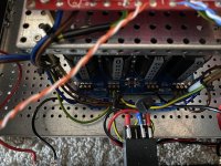
Here is a picture of the PSU connections. It is basically as 6L6 did it, almost at least. Ground is a direct copy, more or less.
This morning the hum is much lower in volume. This leads me to believe that perhaps DC on the mains make the transformer hum more. But that does not explain me hearing it at the speakers. But, putting my ear close to the transformer, it is the exact same sound as in the speakers, frequency and all. Just aounds the same.
So I suspect magnetic coupling with the FE. Or that the hum is just so loud that it is picked up by the FE. Does that make sense? Messing about in the chassis, the FE seems very susceptible to noise in there.
I did some tests today:
1: shorted inputs. No change
2: connnected the amp to bouth grounded and ungrounded wall sockets. No change
3: moved all gnd cables to same euroblock, except for one of the speaker post negs. No change
4: tried to put some aluminium foil between the transformer and FE. No change.
5: moved the FE 2 inches further away from the transformer.
6: reduced bias to half. No change. So the transformer is not struggling. Maybe it is just bad.
So I sorta feel I am at a loss here. But I also feel my main hypothesis is strengthened: the transformer simply makes so much noise it is picked up by the FE.
I have not tried moving the transformer out of the chassis, pr disconnecting the FE. Will do sowhen I have more time. Now, the hum is not hearable at the listening position, so I can live with it. It must go at one point or another, however =)
If it truly is the transformer noise being picked up by the FE, I might consider a Toroidy and their in house DC blocker.
Thoughts?
Attachments
Last edited:
Biased up to 0,55 amps now. Redid the FE, leaving it to cook good between adjustments. +/- 5mv offset. Dont dare touch the pots now =D Sounds magnificent. Mids, bass and top is amazing. Bass is fantastic! Far better than my old Krell. Even sucked my wife into the music yesterday. Stop her in her tracks.
Last edited:
You are all too correct! =D
Btw, hum seems somewhat reduced after moving back the FE further from the transformer. Also, it is almost gone from the right channel. We’ll see how it goes tonight, when people start using all their hone appliances.
Btw, hum seems somewhat reduced after moving back the FE further from the transformer. Also, it is almost gone from the right channel. We’ll see how it goes tonight, when people start using all their hone appliances.
Last edited:
Yes, to avoid confusion please quote the total bias current.
Another thing you can try is loosen the transformer slightly and try rotating it and see
if the hum changes.
Another thing you can try is loosen the transformer slightly and try rotating it and see
if the hum changes.
Will do. Now that I know how =)
To rotate, I need to add some extra wire. The secondary wires are simply too short to be able to roate it. They are also 8 or 10 awg solid core, so a real hassle to work with.
To rotate, I need to add some extra wire. The secondary wires are simply too short to be able to roate it. They are also 8 or 10 awg solid core, so a real hassle to work with.
Learning as I follow along...
re: stating proper bias. I think I understand now re: quoting bias current for all the output pairs. Is that the case (quoting pairs) because this amp is a push-pull? So, 3 pairs per channel in push-pull with each device at 0V55 (across 1R) => 1A65.
If this were an SE output stage with 6 devices - no "pairs" per se, would the proper way to state it be 3A30?
Dissipation would still be the same calc for both, correct?
Edited - Wait... Andy are you using 0R47 or 1R source resistors? If 0R47... Ignore my ignorance. Sorry... still learning...
Last edited:
That's too bad. Often the transformer wires are long enough to allow some rotation.
The field from the transformer is not circular and by rotating you can often find a
direction where the hum pick up is less.
The field from the transformer is not circular and by rotating you can often find a
direction where the hum pick up is less.
Learning as I follow along...
re: stating proper bias. I think I understand now re: quoting bias current for all the output pairs. Is that the case (quoting pairs) because this amp is a push-pull? So, 3 pairs per channel in push-pull with each device at 0V55 (across 1R) => 1A65.
If this were an SE output stage with 6 devices - no "pairs" per se, would the proper way to state it be 3A30?
Dissipation would still be the same calc for both, correct?
Edited - Wait... Andy are you using 0R47 or 1R source resistors? Sorry... still learning...
Still using 0,47 ohms. Started out with a target of 0,185v across, meaning 0,39 amps per vertical pair and 1A18 per channel. No heat, boring. So now at 0,260v across, 0,55 amps per pair, and as ZM stated, at 1A65 per channel. This equates to 0,55 across with 1ohm resistors. Measured across one of them, but stated as per vertical pair. As I understand it. The rest of your questions, I too want to know the answers to =)
- Home
- Amplifiers
- Pass Labs
- BA-3 Amplifier illustrated build guide