pics and wiring confirmation
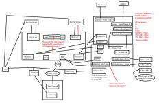
Pics and quick wiring diagram attached. Sorry for awful quality!
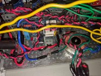
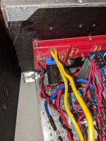
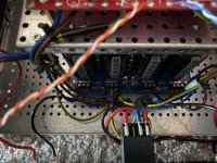
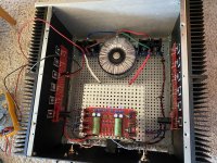
Also, I know this wiring is quite messy. It is not in its final form. I have done alot of "chop-sticking" to poke wires around to see if the motorboating goes away or changes but it has never had an effect. The wires are currently longer than necessary for 2 reasons:
1.) I used to have the PSU in a separate chassis with DC umbilical between, but when I first tested and found motorboating I co-located the PSU with the amp to rule out the DC umbilical and the more complicated 2-chassis grounding.
2.) I needed them long enough to attached to the leads from my benchtop PSU but I will shorten them up once I get this motorboating fixed and complete final assembly.
Should I NOT be twisting DC wires together? I have read horrifically contradictory information online about twisting DC wires. I have a general understanding of why you would want to twist DC wires together in differential pairs carrying HF digital symbols, but haven't found good guidance on this for DC Power wires.
The DC Protection board is currently not used, it's just in the pictures.
The Motorboating happens with the DC Protection mini-trafo completely removed from the mix, so I don't think that is the cause of the problem.
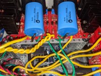
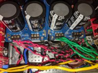
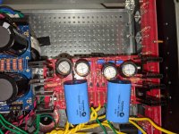
I know you can't see it in the picture, but R5 on the FE boards is connected via a 200ohm on the bottom side of the board (and it's padded with electrical tape so it doesn't touch anything).
I know the smaller caps on the FE are sticking off the board. They are too wide to fit flush against the board. I have the leads as short as I could make them, and the leads are thoroughly padded with electrical tape to prevent anything from touching. If this is a problem I can get smaller caps and swap those out?
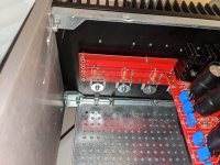
There are some questions in my wiring diagram that i'm uncertain about. I have seen the L/R GND on the DIY PSU boards tied together in like 3 different ways in various guides/pics...
Some people do it on the side by the input, some people do it on the side by the output. Some people do both. To me, it makes the most sense to tie them on the output side where connect ST_GND to chassis, but in the 6L6 guide he ties them by the input so that's what I did. I actually had them tied by BOTH the input and output initially, but thought maybe that made some sort of ground loop, so I clipped the jumper by the output side (but obviously it had no effect).
Also, where should the nominal Audio Input GND connection (that would go to the shield pin on RCAs in a standard stereo config) go?
From my reading of the Grounding guide thread here on the forums, I think they should just go to GND? I have tried moving them to various GND points (on the PSU, or straight to the STAR GND on the chassis) and letting them float but nothing seems to have an effect on the motorboating.
Final wiring question is, are the Output Stage and Bias boards really not connected to PSU GND or ST_GND? I don't see them having a GND connection of any kind, nor do I see them being grounded in any manner in the build guide/pics. This just seems crazy to me, but I am by no means an electrical engineer!
Thanks in advance for your help. Let me know if you need more pics. I can do more disassembly of the chassis to get better pics, I just hate removing things once they're installed!
Pics and quick wiring diagram attached. Sorry for awful quality!
Also, I know this wiring is quite messy. It is not in its final form. I have done alot of "chop-sticking" to poke wires around to see if the motorboating goes away or changes but it has never had an effect. The wires are currently longer than necessary for 2 reasons:
1.) I used to have the PSU in a separate chassis with DC umbilical between, but when I first tested and found motorboating I co-located the PSU with the amp to rule out the DC umbilical and the more complicated 2-chassis grounding.
2.) I needed them long enough to attached to the leads from my benchtop PSU but I will shorten them up once I get this motorboating fixed and complete final assembly.
Should I NOT be twisting DC wires together? I have read horrifically contradictory information online about twisting DC wires. I have a general understanding of why you would want to twist DC wires together in differential pairs carrying HF digital symbols, but haven't found good guidance on this for DC Power wires.
The DC Protection board is currently not used, it's just in the pictures.
The Motorboating happens with the DC Protection mini-trafo completely removed from the mix, so I don't think that is the cause of the problem.
I know you can't see it in the picture, but R5 on the FE boards is connected via a 200ohm on the bottom side of the board (and it's padded with electrical tape so it doesn't touch anything).
I know the smaller caps on the FE are sticking off the board. They are too wide to fit flush against the board. I have the leads as short as I could make them, and the leads are thoroughly padded with electrical tape to prevent anything from touching. If this is a problem I can get smaller caps and swap those out?
There are some questions in my wiring diagram that i'm uncertain about. I have seen the L/R GND on the DIY PSU boards tied together in like 3 different ways in various guides/pics...
Some people do it on the side by the input, some people do it on the side by the output. Some people do both. To me, it makes the most sense to tie them on the output side where connect ST_GND to chassis, but in the 6L6 guide he ties them by the input so that's what I did. I actually had them tied by BOTH the input and output initially, but thought maybe that made some sort of ground loop, so I clipped the jumper by the output side (but obviously it had no effect).
Also, where should the nominal Audio Input GND connection (that would go to the shield pin on RCAs in a standard stereo config) go?
From my reading of the Grounding guide thread here on the forums, I think they should just go to GND? I have tried moving them to various GND points (on the PSU, or straight to the STAR GND on the chassis) and letting them float but nothing seems to have an effect on the motorboating.
Final wiring question is, are the Output Stage and Bias boards really not connected to PSU GND or ST_GND? I don't see them having a GND connection of any kind, nor do I see them being grounded in any manner in the build guide/pics. This just seems crazy to me, but I am by no means an electrical engineer!
Thanks in advance for your help. Let me know if you need more pics. I can do more disassembly of the chassis to get better pics, I just hate removing things once they're installed!
Attachments
-
 wire diagram.png104.6 KB · Views: 249
 -
 PXL_20201123_011111534.jpg1,005.1 KB · Views: 253
 -
 PXL_20201123_010741519.jpg988.6 KB · Views: 253
 -
 PXL_20201123_005147065.jpg982 KB · Views: 267
 -
 PXL_20201123_005216506.jpg670 KB · Views: 220
 -
 PXL_20201123_005130988.jpg999.5 KB · Views: 180
 -
 PXL_20201123_005154153.jpg981.1 KB · Views: 171
 -
 PXL_20201123_005206496.jpg980.1 KB · Views: 138
first thing - what kind of speaker protection circuit you are using - it must be made for balanced amp (sense side ground-free)
second - with so much wires flying everywhere, my mind would go motorboating, let alone amp itself
third - post exact schematic you're using, just so we are all on the same page
second - with so much wires flying everywhere, my mind would go motorboating, let alone amp itself
third - post exact schematic you're using, just so we are all on the same page
https://cdn.shopify.com/s/files/1/1006/5046/products/DSC_0428_large.png?v=1448507826
ZM and Dennis: Linked here is a pic of the PSU V3 front side. Quality is not very good, but it is possible to see the important things for this discussion: the grounding points.
There are two grouped solder pad areas to make ground junctions, one in the middle at the receiving end from the secondaries, and one on the oppsite end, between positive and negative outputs.
Now, what seems to be normal practice, is to put in as many jumpers as possible, effectively making two ground junction areas. This is not the way Andrew (Hifisonix) recommend it be done in his article on the subject of ground loops.
Also, you can see too different ground connection areas at the output section. They are the two middle solder pad groups, one on the neg and one on the pos PCB. Now, I do not see that this PCB really enables one to make a onboard true star or T grounding scheme. Maybe I do not get it, but as far as I can see, there is no sensible way to ensure the junction takes care of the ground currents between the boards, while at the same time protecting signal returns from the same currents. But I might be getting this wrong.
I am posting this pic on ZMs request, and this follows the discussion regarding my mild audible hum issue. Despite further testing, I have not come up with a cure as of yet. Nothing I do seems to alter the hum. I am beginning to arrive at the conclusion that the transformer might have an issue, perhaps capacative coupling between primary and secondary windings (magnetic field coupling). But I really am at a loss, and about to order a new transformer.
Regards,
Andreas
Last edited:
Hi Andreas,
Please post photos of your amp so that members can see how your various
components are wired together. This may help others spot potential problems.
Also, please confirm what your is your current issue. Is it just a hum from the
speakers or is there still a mechanical buzzing from the transformer?
Cheers,
Dennis
You are right, Dennis. But right now all I have are pics I think I allready posted. Since I do not have time to take new ones right now, here they are again.
It is basically wired about the same way 6L6 did it in the guide. But ZM just told me the FE should be powered by daisy chains from the OS.
I made a couple of changes after this pic was taken: left speaker return is now in the same euroblock as all the other returns and gnd wires. Also, i have tightened the secondary wires close together.
Attachments
Have you disconnected one amp channel (remove entirely from PSU) to see if the hum is still present when there is no possibility of ground loop?
Also, are the front-end mosfet heatsinks touching the mounting screws? It’s difficult to see. If they are, please change that.
Also, are the front-end mosfet heatsinks touching the mounting screws? It’s difficult to see. If they are, please change that.
Thanks, 6L6!
Testing with only one channel I have not yet done, I believe. And yes, I have been thinking about those screws. It is really difficult to see. I have electrically disconnected the FE using nylon standoofs. Before that, the FE reacted when touching the riser panel under it.
Not with change in the hum though. Also, I measured a few MV DC between riser panel and chassis ground. Gone now, but that might just be it. I’ll get on it tonight =)
Last edited:
Hi Andreas,
Please post photos of your amp so that members can see how your various
components are wired together. This may help others spot potential problems.
Also, please confirm what your is your current issue. Is it just a hum from the
speakers or is there still a mechanical buzzing from the transformer?
Cheers,
Dennis
Forgot to answer your question...
The current issue is 50-60hz hum that is audible in my 91db sens speakers. I can hear it when I put my ear in front of the driver. Not from the listening position. At first, the hum was a bit louder in the left speaker than the right. I could actually hear it from the listening position. After connecting the negative rectifier correctly, swapping + for return from the secondaries, the hum became less audible, and is equally loud in both speakers.
Putting my ear towards the chassis and transformer, the exact same hum is present. There is NO hum turning the amp on, apart from from the tranny. Then, as the FE gets biased up, it spreads to the speakers.
Thinking of ordering the a new tranny today. Should I?
I decided to isolate or remove the mounting screws touching the FE heatsinks (touching somewhere, some places not, but sinks should not be conductive anyways), and daisy chain power from OS to FE iaw ZMs advice. But I fail to see those things being able to fix this. But maybe so?
Regards,
Andreas
Last edited:
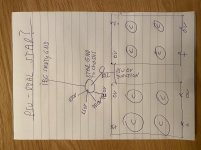
Zen Mod: Iaw our PM discussion, would this be the proper way to make a true star or T gnd out of the DIYAudio PSU, or am I still missing something?
The lines out of the chassis connection point star is: Right and left speaker returns, and FE left and right returns, and on the bottom, safety gnd to IEC Connected on top is NTC, then speaker returns (high current), then FE returns, then chassis.
I somehow feel doing this in reality makes signal gnd and chassis gnd the same thing. But if this is the best I will give it a shot.
Waiting for a more educated assessment.
Attachments
Last edited:
PSU 0V junction directly to the star ground, then star ground to thermistor, then to chassis.
Star ground is not connected to chassis. IEC ground is connected to chassis and thermistor is connected to chassis at same point.
Star ground is not connected to chassis. IEC ground is connected to chassis and thermistor is connected to chassis at same point.
Last edited:
to andynor
Hello Andy,
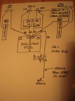
I make my connections the same way like you did - one exception:
I go from mid PSU (0 V = audio ground) over the groundloopbreaker
(35A bridgerectifier+CL60) to IEC-inlet ground/case.
So, my audioground is slightly floating.
I have added a sketch....😕
Don't ask me if this is the right way???
Greets
Dirk
Hello Andy,
I make my connections the same way like you did - one exception:
I go from mid PSU (0 V = audio ground) over the groundloopbreaker
(35A bridgerectifier+CL60) to IEC-inlet ground/case.
So, my audioground is slightly floating.
I have added a sketch....😕
Don't ask me if this is the right way???
Greets
Dirk
Attachments
PSU 0V junction directly to the star ground, then star ground to thermistor, then to chassis.
Star ground is not connected to chassis. IEC ground is connected to chassis and thermistor is connected to chassis at same point.
Thanks for clarifying. The way you describe, is how I have done it in my amp, and it also correlates with 6L6s way of doing it. Was thinking about testing the method I have sketched, but I guess not 🙂
Hello Andy,
I make my connections the same way like you did - one exception:
I go from mid PSU (0 V = audio ground) over the groundloopbreaker
(35A bridgerectifier+CL60) to IEC-inlet ground/case.
So, my audioground is slightly floating.
I have added a sketch....😕
Don't ask me if this is the right way???
Greets
Dirk
The bridge rectifier ground loop breaker I have not tested, and not even considered. What made you choose to do it like that? I have seen it here and there, but never really understood it.
Regards,
Andreas
follow cubicincher's drawing as prayer
if you don't want to use ground-breaker in form of bridge-etc. , just use NTC as you already did
re-read few times both posts here and my replies in PM, and remember what we said about chassis ............. chassis is on safety GND, while everything else is on audio GND
if you don't want to use ground-breaker in form of bridge-etc. , just use NTC as you already did
re-read few times both posts here and my replies in PM, and remember what we said about chassis ............. chassis is on safety GND, while everything else is on audio GND
https://cdn.shopify.com/s/files/1/1006/5046/products/DSC_0428_large.png?v=1448507826
ZM and Dennis: Linked here is a pic of the PSU V3 front side. Quality is not very good, but it is possible to see the important things for this discussion: the grounding points.
There are two grouped solder pad areas to make ground junctions, one in the middle at the receiving end from the secondaries, and one on the oppsite end, between positive and negative outputs.
Now, what seems to be normal practice, is to put in as many jumpers as possible, effectively making two ground junction areas. This is not the way Andrew (Hifisonix) recommend it be done in his article on the subject of ground loops.
Also, you can see too different ground connection areas at the output section. They are the two middle solder pad groups, one on the neg and one on the pos PCB. Now, I do not see that this PCB really enables one to make a onboard true star or T grounding scheme. Maybe I do not get it, but as far as I can see, there is no sensible way to ensure the junction takes care of the ground currents between the boards, while at the same time protecting signal returns from the same currents. But I might be getting this wrong.
I am posting this pic on ZMs request, and this follows the discussion regarding my mild audible hum issue. Despite further testing, I have not come up with a cure as of yet. Nothing I do seems to alter the hum. I am beginning to arrive at the conclusion that the transformer might have an issue, perhaps capacative coupling between primary and secondary windings (magnetic field coupling). But I really am at a loss, and about to order a new transformer.
Regards,
Andreas
Looking at your pics, I note differences in wiring and layout compared to 6l6 or my build. while this isnt unusual, when commenting about hum, the difference is sometimes in the details.
Differences I note, first your output boards and outputs are upside down. Again, not critical and may have no bearing but these are merely differences...but things are different than the 6L6 layout. I am not saying that method is better/worse, just noting differences.
You also didnt mount the BA3 board on the back panel. I thought this to be an excellent choice on 6l6's part, doesnt waste space or require the riser, plus it orients the board as if the transformer were mounted vertical (with respect to orientation of boards to transformer), which likely is hum reducing, but I'll be the first to say I dont know it would help with hum, just noting differences.
Again, not a criticism, you could redo your amp this way and it may not help in the least, but this amp as shown is very quiet.
Russellc
Attachments
![IMG_4810[1].JPG](/community/data/attachments/823/823629-17e135bde57a9f7f34e64d64ceb7f5fd.jpg?hash=F-E1veV6n3)
![IMG_4811[1].JPG](/community/data/attachments/823/823700-772af0501a7a61575bcce797f3b27ff7.jpg?hash=dyrwUBp6YV)
Last edited:
Andreas,
Your picture in your post #585 shows the AC line from the IEC running along the left side of the chassis, close to the left channel power and speaker wires. That may or may not be adding to your hum but it is best to keep AC lines away from DC and signal wires. The best place for the AC from IEC to transformer is straight from IEC to transformer, down the the middle of the chassis.

Your picture in your post #585 shows the AC line from the IEC running along the left side of the chassis, close to the left channel power and speaker wires. That may or may not be adding to your hum but it is best to keep AC lines away from DC and signal wires. The best place for the AC from IEC to transformer is straight from IEC to transformer, down the the middle of the chassis.
Differences I note, first your output boards and outputs are upside down.
...
Russellc
While that by itself shouldn't be the cause of the hum, it's good to point that
out since having the mosfets above mid-line can lower the heatsink
efficiency.
Great, REALLY great, guys. Thanks everybody for helping me!
I should first mention that I now need to be as close as 20-15 centimeters (6-8 inches from the driver before any hum can be heard.
This is most likely a ground issue, so I will continue to work on that path.
Regarding AC line: I too have thought of that. I even pulled it out of the chassis, put yo no avail: still hum.
Regard FE orientation, as Russel comments: I put the FE like that to access bias pots easier, and also, i figure it might provide a more even temperature across the whole board. I have, as late as today, been considering moving it. However, I have lifted it up while live, holding the riser, moving it back and forth, and reorienting, but to no avail. No change.
Dennis: I have read different opinions on whether to mount transistors low or high, so decided to try this. But I have allready decided to change them to 6L6 and Russels way. I will however wait until new fets arrive, cause I am going to redo a whole sink. Switch em both then.
So what did I do today?
1: I now power the FE from the output bias bords through daisychaining. Well, the hum is less now, and the sound cleaner. So that was a good tip. Thanks, ZM.
And thanks to all of you!
As of now, the hum cannot be said to bother me. At least not in practical listening.
All of your good advice will be considered acting upon once I redo that sink. What I can say, is the work today bore fruits.
I also tried to try and split the FE returns to different sides of the PSU. This caused increased hum in one channel, no change in the other. So I kinda landed on this being a ground issue. If the transformer is contributing, maybe, I dunno. But I am quite sure it does not help. Will post new pics once the setup lands a bit more. There is some wiring right now thats just temporary.
Cheers and all, tonight I will have a small beer I think.
Last edited:
to andynor #594
Hello Andy,
Why I am doing the grounding with groundloopbreaker this way? 😕
I have learned this from studying PSU-schematics from Nelson Pass. 😀
But I can't be sure that it solves your hum -problem?
And I used it in all of my amp builds with very good results.
Greets
Dirk
Hello Andy,
Why I am doing the grounding with groundloopbreaker this way? 😕
I have learned this from studying PSU-schematics from Nelson Pass. 😀
But I can't be sure that it solves your hum -problem?
And I used it in all of my amp builds with very good results.
Greets
Dirk
- Home
- Amplifiers
- Pass Labs
- BA-3 Amplifier illustrated build guide