Wow..guess what? Only one side is glowing..Thanks for the quick diagnostics. Do I just replace the tube or should I check for what cause the failure.
Thanks again....
Thanks again....
Most likely you need a new tube. You can check first to be sure. Measure the voltage between test point T5 and Ground on the board. If it measures around 9VDC, then there is power at the filament, the filament isn't working, and a new tube is needed.
By the way, do you leave the preamp powered on all the time or is it turned off between listening sessions?
And one last Hail Mary check are the solder joints.
By the way, do you leave the preamp powered on all the time or is it turned off between listening sessions?
And one last Hail Mary check are the solder joints.
First thing I did was check the connections, I will pull out the circuit board tonight and test the voltage as you suggested and check properly.
I was on vacation for 5 weeks and I think I left the preamp on...I normally would just leave the preamp on as suggested by people on the forum.
Thanks
I was on vacation for 5 weeks and I think I left the preamp on...I normally would just leave the preamp on as suggested by people on the forum.
Thanks
The expected service life of the Nutube when used continuously is 30,000 hours. That is 1250 days or 3.42 years.
I normally would just leave the preamp on as suggested by people on the forum.
that's sacrilege even if using "normal" tubes
you can think of that with pure sand preamps .... no wear no tear; whoever said that to you regarding tube preamp is not your friend

It sure seems that left channel has some vulnerability for a currently unknown reason.
As someone who loves my Korg B1, is there anything we can do to reduce the risk? Surely turning the unit off when not in use is one option that likely reduces the risk. Does adding a SMPS filter, like the one from the store, add any protection?
As someone who loves my Korg B1, is there anything we can do to reduce the risk? Surely turning the unit off when not in use is one option that likely reduces the risk. Does adding a SMPS filter, like the one from the store, add any protection?
Can anything be done at all, shy of never plugging it in?
Edit: I ask as I have a few Korg B1's, one given as a gift to family member and if there's something I can do to provide some protection, it likely is worth some effort. I just happen to have the SMPS filter from the store on all of them, which I had hope might do something, but alas, no joy there.
Edit: I ask as I have a few Korg B1's, one given as a gift to family member and if there's something I can do to provide some protection, it likely is worth some effort. I just happen to have the SMPS filter from the store on all of them, which I had hope might do something, but alas, no joy there.
Last edited:
Can anything be done at all,
maaaaaaaybe worth trying, as last attempt of indulging puny blind DVD screen, is to introduce soft start heating circuit
Thanks ZM! I'm willing to try it out! I suspect no one has turned this schematic into a PCB yet to try out.
I'm taking a PCB design short course right now at a local community college. Im a comete noob at KiCaD. Is this something I can do for extra credit if it may benefit the Korg B1 diyaudio community? I'm willing to give it a try. I don't mind screwing up and having everyone tell me where I went wrong.
Edit: Since the failures seem to happen while the preamp is left on, does a "soft start" provide protection both for warm up and long term running?
Edit: Since the failures seem to happen while the preamp is left on, does a "soft start" provide protection both for warm up and long term running?
if you're married, you know that question as that only your wife can answer

I reckon Papa's solution with zener is reg stable enough and precise enough; though, as old saying goes - Bad Rooster is obstructed even with a Feather ....... so, if Korg tube is destined to go poof, there is no protection from that
besides soft start and then voltage stability, one can't do more
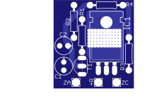
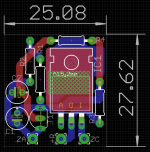
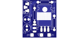
said circuit with LM317 can be made on small veroboard, as two-pin thingie and can be inserted in place of zeners...... so no need for main pcb change at all
edit - just tiny xacto knife hoorah! on original pcb should be needed, to isolate present zener cathode trace from +R output trace
Last edited:
said circuit with LM317 can be made on small veroboard
implementation is easypeasy
this, fast and dirty; it can be made nicer, but must zzzzzz
Attachments

The filament is rated at 0.7V and 17mA.
The Korg Nutube filament circuit has a 470 Ohm resistor in series with the filament, and the filament voltage is regulated by a 9.1V zener diode. The zener has a tolerance of 5% so it can be as high as 9.56V. Unfortunately this is not a good thing because if the filament draws 17ma, the filament will see a voltage of 9.56V- 0.017A x 470 Ohm = 1.57V. This is much higher than the specified rating of 0.7V.
So it would definitely help the filament if the filament voltage and current is measured, and if the voltage is too high, adjust/change the zener diode and/or resistor to get the filament voltage to 0.7V.
A zener diode on the low end of the voltage tolerance range is better for the filament than a zener diode on the high end of the voltage tolerance range.
Last edited:
So it would definitely help the filament if the filament voltage and current is measured
definitely
so, morning coffee time, morning is smarter than night yadayda
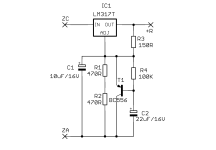
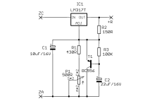
here it is, adjustable
monitor voltage at heaters (as Ben said 700mV is magic figure!!), twiddledee with trimpot to get it exact, et voila!
voltage with zener substitution is adjustable from 9V0 to 4V83
if R1 is 750R and P1 is 200R, then voltage span is lesser (finer twiddledee), from 9V16 to 7V5
do not forget that is necessary to cut +R trace at appropriate place on original pcb and then fed output side of it from +R pad on small pcb
Attachments


Last edited:
Just checked the voltage on T5 and is 8.9VDC. I purchased the kit in May 2024 and probably finished building in July 2024, so the tubes do not have much hours on it. I am going to order another set of tubes and replace them. Hope the new ones last longer.
Thanks for all the info everyone has contributed...
Thanks for all the info everyone has contributed...
My heater voltage is just above 0.6V.
Could it be worth it, sonically noticeable to add Zens reg. circuit and lift the heater voltage to 0,7V?
To be honest, i will probably add it just for fun, anyways. But it is interesting to hear if there are some tube skilled dudes that know anything about heater voltage and what sonic differences 0,1 volt possibly would result in. 🙂
Last edited:
@ClaudeG linear smd b1k nutube is implemented in my friends dac.

First remark, when someone farts in the movie you can smell it 🤣
Music wise, there are more noticable details which weren't heard before, more refined sound, and 3d stage is much clearer now.
General conclusion, audibly better than with smps. Which is a nice improvement since the smd design sounds a lot better than default one.
I have one more idea in mind, which i currently don't have time to design. But in general even smaller board, without post supply crcrc and passive drop, all tps7a4701 regulated close to load. Which should bring this to another level, but at that point it couldn't be called b1k nutube. This was done as homage to pops.
My heater voltage is just above 0.6V.
Could it be worth it, sonically noticeable to add Zens reg. circuit and lift the heater voltage to 0,7V?
To be honest, i will probably add it just for fun, anyways. But it is interesting to hear if there are some tube skilled dudes that know anything about heater voltage and what sonic differences 0,1 volt possibly would result in. 🙂
Korg Nutube spec sheet says filament voltage: MIN 0.6V TYP 0.7V MAX 0.8V
So you are good. I would suggest a bit low is better for the filament longevity.
- Home
- Amplifiers
- Pass Labs
- B1 with Korg Triode