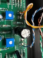
I am currently building this pre-amp. I've reached the PSU testing step and have run into some issues: 1) I am reading 8.86 V across the diode; 2) the LED power indicator does not illuminate. Is my voltage reading within spec? What could be the issue with the LED?
Attachments
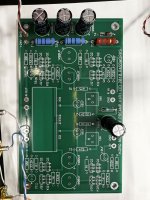

8.86V is within the specification for the 9.1V zener diode.
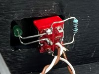
The LED polarity may be incorrect as rikiheck suggested, or it may be damaged, or it may not be getting voltage. To check for voltage, place the meter probes on the LED leads and measure DC voltage. If DC voltage is there, then remove LED and reverse the leads. You can check by holding the leads to the switch terminals. If it does not light up then it is probably damaged.
The LED polarity may be incorrect as rikiheck suggested, or it may be damaged, or it may not be getting voltage. To check for voltage, place the meter probes on the LED leads and measure DC voltage. If DC voltage is there, then remove LED and reverse the leads. You can check by holding the leads to the switch terminals. If it does not light up then it is probably damaged.
How many times has that happened to me? Hell, the other day, I switched off the wrong breaker, and guess what? It has been years since my last awakening.
While everything is "possible" - I modified mine to have an other output to drive without problem 600Ohm headphones - I would say generaly speaking B1K is not made for driving HP directly.
Key words are output impedance vs HP impedance and also low cut frequency (bass cut off) in what becomes an output RC filter (that's easier to address, just a cap to adjust / capacity to increase).
It could work with some mods with 300R HP, not sure how it would with 38R ones (well,you would still get "tones" out of it LOL).
In every case you need to know exactly what you are doing... well, I guess if you would, you wouldn't have asked probably.
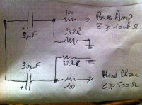
Attached is the HP output modification I did- from there on you need to build yourself your own modifications if you still wish to carry on.
Good luck!
Claude
Key words are output impedance vs HP impedance and also low cut frequency (bass cut off) in what becomes an output RC filter (that's easier to address, just a cap to adjust / capacity to increase).
It could work with some mods with 300R HP, not sure how it would with 38R ones (well,you would still get "tones" out of it LOL).
In every case you need to know exactly what you are doing... well, I guess if you would, you wouldn't have asked probably.
Attached is the HP output modification I did- from there on you need to build yourself your own modifications if you still wish to carry on.
Good luck!
Claude
Attachments
Last edited:
Note...
From memory, I went from 30uF to 100uF or 150uF because that's what I had on hand re output caps, and while I carried a short functional test, to my amazement the B1K drove my test HP including with some bass (Koss with no real bass though, their impedance is something around 50R I believe, they are quite efficient though (require not much power). Remains it is defo a low impedance load for B1K...
It is all down to what you want and use, it can work in some circumstances (it does for my 2 HP to my amazement), but again, B1K isn't a HP amp per se.
I hope this helped
Claude
Note 2...
On the attached file 2 posts above, if you want to refer to the original B1K schematic and not my very own caps mods, consider the top section to be the orignal B1K output (eg to a power amp) and the 3uF cap to be in fact 10uF in Papa's schematic.
I hope this helps
Claude
On the attached file 2 posts above, if you want to refer to the original B1K schematic and not my very own caps mods, consider the top section to be the orignal B1K output (eg to a power amp) and the 3uF cap to be in fact 10uF in Papa's schematic.
I hope this helps
Claude
I'm stuffing the kit transistors. All are marked J113, but four are marked FKH33 and four are marked WH44. Are they all the same, or do they have different values? If they're different, which go where?
They have been matched don't worry. Those are just batch numbers. Just follow the instructions 🙂
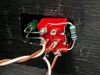
I finished, and it sounds great! I do have one issue: the volume knob is reversed - no sound is all the way to the right, loudest is all the way to the left. As far as I can tell, I have everything wired correctly. What could be the issue?
Attachments

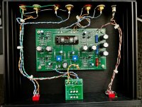
You mounted the pot on other side of the adapter pcb 🙂
I happened to be on the conference call when the creator of this little PCB exclaimed "Oh! Oh! Oh! We can put silkscreen text right on the board itself, saying MOUNT POT THIS SIDE , to prevent a common type of assembly error!"
It only happened to me ....uh....one time. Desoldering all those pins was no fun.
@ottokar790 take care to not overheat the traces when you desolder.....or, better yet....maybe just rewire in place as is and ignore the silkscreen....sharpie the new pin names.
@ottokar790 take care to not overheat the traces when you desolder.....or, better yet....maybe just rewire in place as is and ignore the silkscreen....sharpie the new pin names.
- Home
- Amplifiers
- Pass Labs
- B1 with Korg Triode