As far as I can tell, the circuits surrounding the Nutube are working correctly, so unfortunately it points to a bad channel in the Nutube. The bad channel is still functioning but not at full strength, as its current output is reduced.
Thank you again Ben, I ordered a replacement Nutube and I'll report back once its here and installed.
Drop check rated Korg triode. During this totally intentional and not at all accidental impact test, the B1 survived a 4' freefall and impact with a concrete floor. The crumple zone pins and vacuum suspension took over after the solder hinge dispersed the brunt of Mr. Newton. Whether the unit will power up is unknown.
Attachments
I got the new Nutube in today, and unfortunately, there is no change on the voltage. Lowest it will go is about 13.9...
It's hard to believe that two Nutubes have exactly the same issue, especially since one is new, so the issue must be within the board.
Recheck that you are getting 24V power at the right channel, that all other TP voltages are correct. Previous check of the filament voltage was correct and with proper current flow. Previous check of the bias voltage adjustment showed that the bias voltage adjustment was working. With the new Nutube in place, check those again. Recheck all solder joints and redo any that look suspect.
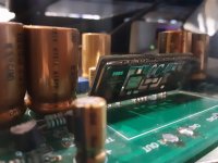
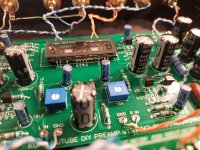
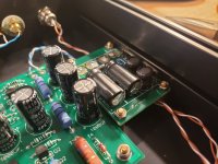
There are not many components. Check resistors again for correct value. Your board and small components are not easy to see because of the large capacitors blocking the view so it is impossible to check over the internet.
The other active components are the JFETs. If you have an extra J113, replace J1 at the output.
Recheck that you are getting 24V power at the right channel, that all other TP voltages are correct. Previous check of the filament voltage was correct and with proper current flow. Previous check of the bias voltage adjustment showed that the bias voltage adjustment was working. With the new Nutube in place, check those again. Recheck all solder joints and redo any that look suspect.
There are not many components. Check resistors again for correct value. Your board and small components are not easy to see because of the large capacitors blocking the view so it is impossible to check over the internet.
The other active components are the JFETs. If you have an extra J113, replace J1 at the output.

if I recall correctly, mine came with at least one extra. I still have them I think, not able to check but I recall being so surprised. not Sure whether it was B1K or NP crossover. keep Us posted
I like to throw in an extra - saves me the occasional line at the post office.

I received a brown black brown red red resistor for R1 instead of brown black black green black. Are these interchangeable? Also my kit came with color coded resistors. Does anyone here have the chart that shows the values?
R1's value is specific to the individual JFETs. The value won't always be the same. If it came with them in the little package with the JFETS, then they should be good to go.
If you have the diyAudio kit, the value of the R1 is matched to the JFETs that come with the kit. There is no standard value of R1.
An internet search will yield numerous resistor colour code charts and even calculators.
Or you can use the resistance function on your multimeter.
An internet search will yield numerous resistor colour code charts and even calculators.
Or you can use the resistance function on your multimeter.
I frequent this one quite a bit:
https://www.digikey.com/en/resource...ors/conversion-calculator-resistor-color-code
You will see the selection for 4, 5 and 6-band resistors.
https://www.digikey.com/en/resource...ors/conversion-calculator-resistor-color-code
You will see the selection for 4, 5 and 6-band resistors.
hi guys, what do I need to adjust to turn the board into a headphone amp? I have the nutube and a pair of ~17mA matched LSK389 jfet
Probably was discussed, but can not find, sorry: is it possible to achieve same 1-1.5% THD H2/H3 -20db, neg. phase, but not at 1V but rather 2V output? Or another word same THD characteristics, but lower THD values at given output voltage. Thank you!
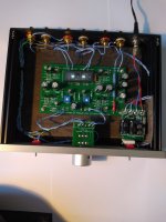
Hi guys. I'm having some issues with my preamp. I'm only getting a signal in one channel (left working, right not working). I am wondering if I wired something wrong.
Attachments
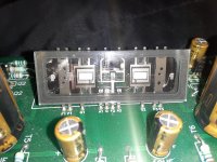
What are you testing on T7 and T8? Also, are both sides of the tubes lighting up evenly?
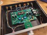
You can go through all of the other test points and give us the results if you like. I didn't spot any issues with wiring right off the bat.
Make sure your grounds are hooked up to the right spots on the ALPS. Looking at the other wiring, everything looks right as far as I can tell.
A bit of an awkward angle, but if you are able to get a pic of the wiring top and bottom of the pot, that would help.
I will get back to you on the test points. Both sides of the tube light up.
I double checked the wiring on the pot and it looks fine.
I double checked the wiring on the pot and it looks fine.
if you tap on the tube (gently) you will hear ringing. If the ringing is making it out to both channels, then the problem probably lies before the tube whether it be wiring, loose connection etc. You can also switch your interconnects from the functioning side to the non-functioning side going in and out of the preamp just to knock that out.
I will try that. Here are my readings for T1 - T8
T1 - 24v
T2 - 23v
T3 - 22
T4 - 9v
T5 - 0.6v
T6 - 0.6v
T7 - 14.5v
T8 - 16.1v
T1 - 24v
T2 - 23v
T3 - 22
T4 - 9v
T5 - 0.6v
T6 - 0.6v
T7 - 14.5v
T8 - 16.1v
Adjust T7 and T8 to around 9.5-10v with the trimmer pots. You can adjust these to taste later but that is a safe starting point. All the test points look good to me otherwise. t1-4 are power supply related which seem to be good which figures since one channel works. T5 and t6 indicate that the tube should be working properly. T7 and T8 are the bias of each channel.
I would go through your wiring and make sure all of that is good. Make sure no ground is touching the in or out leads anywhere. Also that none of the in/out leads are making contact with one another.
I would go through your wiring and make sure all of that is good. Make sure no ground is touching the in or out leads anywhere. Also that none of the in/out leads are making contact with one another.
I resoldered the joints at the tube and a few others. Retested it and it's working on both channels! Thank you very much for the help Mike. Glad it wasn't an issue with any of the parts 🙂
- Home
- Amplifiers
- Pass Labs
- B1 with Korg Triode