Ben, yes, your comments are correct.
Yes, the preamp was fully functional. I built this unit well over a year ago without any build issues. It operated flawlessly all along. My original problem was that the unit was so microphonic, it was basically unusable. I could clap my hands from a few feet way and it would ring at about 2-3khz in both channels for about 15 seconds regardless of volume setting. I could use it only at very low volume levels. Any time I turned it up, to actually listen to it, it sounding harsh and gritty and very much like cheep electronics with the ringing always just below the surface. The opposite of a relaxing sound. Eventually, I put it on the shelf. I've come back to it twice trying to isolate the board, the nutube, sorbothane feet, etc. This time, I was putting dynamat in the chassis. Still ringing. I admit, I was sloppy when I grounded it. I was experimenting with different materials trying to calm the microphonics. I'll get you some pictures tomorrow when there is good light. Thanks.
Yes, the preamp was fully functional. I built this unit well over a year ago without any build issues. It operated flawlessly all along. My original problem was that the unit was so microphonic, it was basically unusable. I could clap my hands from a few feet way and it would ring at about 2-3khz in both channels for about 15 seconds regardless of volume setting. I could use it only at very low volume levels. Any time I turned it up, to actually listen to it, it sounding harsh and gritty and very much like cheep electronics with the ringing always just below the surface. The opposite of a relaxing sound. Eventually, I put it on the shelf. I've come back to it twice trying to isolate the board, the nutube, sorbothane feet, etc. This time, I was putting dynamat in the chassis. Still ringing. I admit, I was sloppy when I grounded it. I was experimenting with different materials trying to calm the microphonics. I'll get you some pictures tomorrow when there is good light. Thanks.
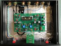
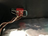
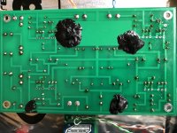
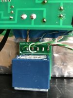
These three are from the bottom. The black goo is unvulcanized butyl rubber. It is a mess. I could remove it if necessary but the unit was functioning fine with it in place before I grounded the resistor. I did not want to use it, but I have been desperate to stop the microphonics. It helped some.
Attachments
Well, this is puzzling. It was working before the shorting incident, now it doesn't. But the voltage measurements are near identical between the channels, yet one channel works and the other doesn't.
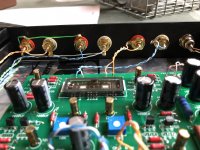
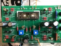
I have looked at your pictures and your placement of resistors is not helpful in trouble shooting. It would have been most helpful if all of the resistors were oriented so that their resistance values were visible, as many issues in the past have been due to mixed-up resistors. However your preamp was working previously so a mix-up of resistors is not likely to have happened.
Now to continue the trouble shooting. The first suggestion is to check for continuity of the signal input line. Please measure the resistance between the input RCA positive pin and the signal input pad on the board (L IN and R IN) for each channel with the power off. And does the resistance vary as you turn the volume knob?
If you have an oscilloscope, apply a signal to the input and trace the signal with the oscilloscope. See where you lose the signal.
Yes, that would be the next step. I have already marked up some test points from input to Nutube. It can be done with a meter set to AC voltage if no oscilloscope.
Run the preamp with a source connected to the input with the volume pot turned up and measure AC voltage relative to Ground.
Be careful with the probes!
Run the preamp with a source connected to the input with the volume pot turned up and measure AC voltage relative to Ground.
Be careful with the probes!
Attachments
OK, step one - no power on the unit. With the volume pot all the way up, I have continuity in both channels from input through the switch and through the pot to the input pads on the board. Impedance of the pot measures about 14kohms at 3 o'clock, about 40kohms at 12 o'clock and about 50kohms at all the way down, about 7 o'clock. this is approx. the same for both channels. also the same through the switch settings. Volume pot moves smoothly. So, I think we can assume we are OK up to the board?
On to the source testing...
On to the source testing...
Looks like your input/selector switch/volume pot circuits are working. You can also check your output wiring from board to RCA out jack.
If all checks out, it is back to the board.
If all checks out, it is back to the board.
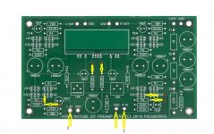
Input signal of 1khz. no load to board = 0.186V. Power off. connected both channels. Volume pot all the way up. V(L in) = 0.186V. V(R in)= 0.005V or effectively shorted on the board. With the power on, the measurements are the same.
pt 1L = 0.186V, 1R = 0.005V
pt 2L = 0.186V, 2R = 0.005V
pt 3L = 0.186V, 3R = 0.005V
pt 4L = 0.186V, 4R = 0.005V
for point #3, I assume you were wanting me to measure the source, (s) on each channel's jfet.
pt 1L = 0.186V, 1R = 0.005V
pt 2L = 0.186V, 2R = 0.005V
pt 3L = 0.186V, 3R = 0.005V
pt 4L = 0.186V, 4R = 0.005V
for point #3, I assume you were wanting me to measure the source, (s) on each channel's jfet.
So the right channel when you measured the resistance between the input RCA positive and the board input with volume at maximum, you measured no resistance, and 50kOhm at volume pot at minimum. That is good. But when you inputted a 1kHz signal into the right channel, you get no signal at the board.
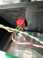
Are you using the same input RCA jack? Check the soldered connections. Or you may have a short to ground somewhere between input RCA and board input.
Edit:
Did you use the same cable to input the 1kHz signal to both channels? Did you input the signal at the RCA jacks? Did you try the other input?
Edit again:
Also measure the resistance between input RCA positive pin and Ground pin of the selected input. Check both inputs.
Last edited:
My input sources are good. I've swapped them, etc. Resistance between RCA input pin and ground is infinite.
Here is what is interesting. With the volume pot all the way down, (max impedance) signal strength to the input of the volume pot is 0.186V for both channels. When I turn up the volume, the left channel input at the pot remains steady at 0.186V all the way up to max volume. But the right channel does not. The right channel will hold that input V to the volume pot up till about 4 o'clock, but then starts to decrease rapidly as the resistance of the pot gets close to zero. At max volume, the signal strength at the volume pot input pulls down to 0.032V on the right. This makes sense to me if there is no resistance to ground beyond the volume pot. With the volume at 3 o'clock, the source is still seeing about 6kohms which is mainly the volume pot. The source has no problem driving this resistance. but if we turn the pot closer to max volume, then the source is seeing mostly the resistance of the board. If the right is shorted, it is pulling down my input source.
Here is what is interesting. With the volume pot all the way down, (max impedance) signal strength to the input of the volume pot is 0.186V for both channels. When I turn up the volume, the left channel input at the pot remains steady at 0.186V all the way up to max volume. But the right channel does not. The right channel will hold that input V to the volume pot up till about 4 o'clock, but then starts to decrease rapidly as the resistance of the pot gets close to zero. At max volume, the signal strength at the volume pot input pulls down to 0.032V on the right. This makes sense to me if there is no resistance to ground beyond the volume pot. With the volume at 3 o'clock, the source is still seeing about 6kohms which is mainly the volume pot. The source has no problem driving this resistance. but if we turn the pot closer to max volume, then the source is seeing mostly the resistance of the board. If the right is shorted, it is pulling down my input source.
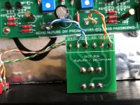
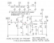
On a related topic, I am positive that the original schematic has an error and does not match how the board as configured. See attached for what I am seeing on the actual board. May or may not be critical to solving my issue, but thought it should be noted.
Attachments
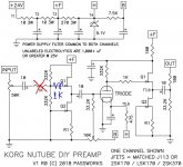
The location of the 1k resistor is not a problem.
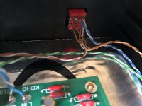
At this point the easiest thing to do is to disconnect the volume pot wires from the preamp board, then connect the good left channel pot output to the right channel preamp board input. Then if the right channel works properly, something is wrong with the volume pot or its wiring.
At this point the easiest thing to do is to disconnect the volume pot wires from the preamp board, then connect the good left channel pot output to the right channel preamp board input. Then if the right channel works properly, something is wrong with the volume pot or its wiring.
Well, son of a gun. Your hunch is correct Ben. It is the volume pot. I moved the functioning left channel wires to the right board input and that rt channel works fine now. I then jumped the source back to the LT channel as well and I have mono music from both channel outputs. Excellent. I would have bet money that the issue was on the main board. Thanks for sticking with me through this issue. Now to replace the volume pot.
Problem isolated, that's good news.
The board measurements were more or less identical between channels so the probability of a board issue was low. You have to go with the evidence. 🙂
The board measurements were more or less identical between channels so the probability of a board issue was low. You have to go with the evidence. 🙂
It is always the volume pot. 😎Well, son of a gun. Your hunch is correct Ben. It is the volume pot. I moved the functioning left channel wires to the right board input and that rt channel works fine now. I then jumped the source back to the LT channel as well and I have mono music from both channel outputs. Excellent. I would have bet money that the issue was on the main board. Thanks for sticking with me through this issue. Now to replace the volume pot.
I had an episode where I could hear my PC mouse moving, which was the source of much ridicule, and it was all because of an annoying ground loop. Resoldering the volume pot solved it.
Note that I said that it may be a problem with the volume pot or its wiring. So remove the pot and check both channels. If you find a problem, then replace it. If the pot is ok, investigate the wiring and connections.
Has anyone tried replacing the stock trimpots with "nicer" multi turn pots?
I opened my B1K after enjoying it for 6 or so months and I noticed the bias had shifted a bit (moving closer to 10V on T7/T8). The stock trimpots arent multi turn so they are super sensitive I find.
I opened my B1K after enjoying it for 6 or so months and I noticed the bias had shifted a bit (moving closer to 10V on T7/T8). The stock trimpots arent multi turn so they are super sensitive I find.
I don't see why you shouldn't if you are having issues 🙂 I belive some did use different trim pots, longer leads to case so they can change bias without opening it. Long thread so don't remember who and when.
Hello ChrisM91,
I have mounted 10-turn pots into my B1 NUTUTBE. I have prolonged from the pcb to the trimpots.
Works like a charm. I have to look for the pics of my B1NUTUBE
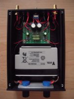
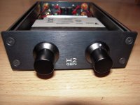
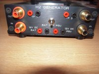
I did the same in my H2-generator... but with two 270 degree-pots to adjust H2 (pos.-neg.).
Cheers
Dirk
I have mounted 10-turn pots into my B1 NUTUTBE. I have prolonged from the pcb to the trimpots.
Works like a charm. I have to look for the pics of my B1NUTUBE
I did the same in my H2-generator... but with two 270 degree-pots to adjust H2 (pos.-neg.).
Cheers
Dirk
Attachments
- Home
- Amplifiers
- Pass Labs
- B1 with Korg Triode