Hi experts:
Is there an easy way to add remote volume control to my B1 w/Korg preamp?
I can solder and follow directions, but need basic hand holding (aka 6L6 build guides).
Thanks
Craig in Seattle
I bought the Muses volume, haven't installed it yet...
https://www.diyaudio.com/community/threads/b1-with-korg-triode.313612/page-374#post-6990164
I had great success with dealing with microphonics. I found two Swedish 10 kroner coins, which are thick brass coins, and taped them directly to the glass with many turns of vulcanic tape around the Korg Nutube. Now I can only hear microphonics when turning it on and off. This makes me want to build more of these.
But the night BEFORE I fixed the microphonics problem, another type of noise appeared. Some type of switching noise is polluting the previous quiet preamp. Pretty ironic.
I might have a lot of switching noise in my system, but my other B1 Triode preamp has no weird switching noise. So something has happened. I can now hear differences in the switching noise when moving my computer mouse. The noise caused by the computer mouse disappears after I disconnect my PC-monitor. But the main switching noise is still there. Mostly in the right speaker.
I tested to start the computer without a graphics card, but the switching noise was still there. The only time it disappears is when I turn the PC off, or the preamp is off, or when I replacee it with the other fully working B1 Triode, using the same original Triad power adapter. Thankfully it is not from the Sony V-fet pt.1 lottery amplifier.
Last edited:
They ways of the Nutube can be mysterious it seems. Have you tried pressing ctl+alt+del while triple clicking the right button of your mouse and singing «Touch me» half an octave below Samantha? I can drop by one day since we live in the same area. My clicking timing is immaculate 
PS: see Papas posts followed up by MZM a few pages back.
regards,
Andy
PS: see Papas posts followed up by MZM a few pages back.
regards,
Andy
You are welcome here. Brace yourself. What triggered microphonics in the preamp was screaming children.They ways of the Nutube can be mysterious it seems. Have you tried pressing ctl+alt+del while triple clicking the right button of your mouse and singing «Touch me» half an octave below Samantha? I can drop by one day since we live in the same area. My clicking timing is immaculate
PS: see Papas posts followed up by MZM a few pages back.
regards,
Andy
Here is me touching my mouse:
Last edited:
I found the likely culprit. I flushed every solder joint until l found out that the ALPS potentiometer had an adapter with screw terminals. The screws were not tightened.

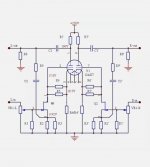
will be great if someone makes another schematic jfet 12ax7 jfet.like B1 korg. or 12sn7.
I tried schematic from eBay enclosed. it's very nice too
i had tried all tubes
tried aleph L. and boz
hybrid is very special. the energy and openess in music is different. imagine being able to roll tubes with B1 12ax7.
I tried schematic from eBay enclosed. it's very nice too
i had tried all tubes
tried aleph L. and boz
hybrid is very special. the energy and openess in music is different. imagine being able to roll tubes with B1 12ax7.
Attachments
Excuse my ignorance... what does R9 do?will be great if someone makes another schematic jfet 12ax7 jfet.like B1 korg. or 12sn7.
I tried schematic from eBay enclosed. it's very nice too
i had tried all tubes
tried aleph L. and boz
hybrid is very special. the energy and openess in music is different. imagine being able to roll tubes with B1 12ax7.
hi friends,
just wanted your confirmation that one side of the Korg tube is dead and I'm not missing something,
after 2 years one side just stopped working, I haven't seen anything weird/burned, etc.
besides the tube light for that side is off
here are the voltage measurements:
T1- 23.9v
T2- 23.1v
T3- 22.2v
T4- 9.4v
T5- 9.4v
T6- 0.7v
T7- 19.9v
T8- 8.9v
Tube legs V:
F1(both)- 9.4v
F3(both)- 0.7v
G1- 2.3v
G2- 2.3v
thank you very much!
🙂
Last edited:
Just flush all the solder points. Maybe the contact where the solder attaches to the pcb board is a bit small in some places, making it easier for cold solder to occur.hi friends,
just wanted your confirmation that one side of the Korg tube is dead and I'm not missing something,
after 2 years one side just stopped working, I haven't seen anything weird/burned, etc.
besides the tube light for that side is off
here are the voltage measurements:
T1- 23.9v
T2- 23.1v
T3- 22.2v
T4- 9.4v
T5- 9.4v
T6- 0.7v
T7- 19.9v
T8- 8.9v
Tube legs V:
F1(both)- 9.4v
F3(both)- 0.7v
G1- 2.3v
G2- 2.3v
thank you very much!
🙂
Your left channel Nutube filament is not conducting current so that is most likely the filament that is not lighting up. You are getting power to the filament pad of the pcb. So either the solder joint at F1 is bad or the left side filament is burned out.
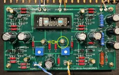
Post some pictures of both sides of the pcb in case there is something else that might be causing the problem.
Post some pictures of both sides of the pcb in case there is something else that might be causing the problem.
Will a DPDT On-Off-On (three position toggle) mini toggle switch work for the selector switch between the two inputs? Or do I need one with just two toggle positions? Thanks.
Your left channel Nutube filament is not conducting current so that is most likely the filament that is not lighting up. You are getting power to the filament pad of the pcb. So either the solder joint at F1 is bad or the left side filament is burned out.
Post some pictures of both sides of the pcb in case there is something else that might be causing the problem.
Just flush all the solder points. Maybe the contact where the solder attaches to the pcb board is a bit small in some places, making it easier for cold solder to occur.
thank you! 🙂
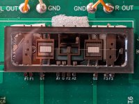
I've flushed all joints and still... then I noticed that the faulty side of the tube has its thin microphonic noise wire broken on the outer side,
attaching a pic, is this it? F1 side
Attachments
Looks like it 🙂thank you! 🙂
I've flushed all joints and still... then I noticed that the faulty side of the tube has its thin microphonic noise wire broken on the outer side,
attaching a pic, is this it? F1 side
That wire is the filament. Unfortunately it looks like the left channel filament is broken. A new Nutube is required.
Hi guys,
I have a problem similar to Skywave-Rider where one side of nutube is much brighter (left side for me), but I don’t have the resistors swapped. At least not at the same points he had on both channels. hmmm what could it be? Please help me debug this issue.
I reflowed the back side of the board before this test. Tomorrow I will go over back and front again.
These are the measurements.
from T1-T6 is spot-on but T7 and T8 becomes very wacky.
T1 = 24.1v
T2 = 23.3v
T3 = 22.5v
T4 = 9.2v
T5 = 0.6v
T6 = 0.6v
T7 = 14.85v
T8 = 4.06v
On the tube legs measures
F1s - 0.66v match
F3s - 0.66v match
G1 = 1.80v
G2 = 3.83v
went ahead and measured these too for DC across R1 and 332k on left and right Channels
L-R1 = 0.80v
R-R1 = 0.77v
L-332k = 6.19v
R-332k = 17.33v


before the debug, I’d like to also say thank you to everyone in the forum. I’ve been lurking a longggg while and (liked to lurk before this first post) have found this place to be quite magical even for the noobs like me. The prominent posters are always very helpful, you know who you are. This is my second project after dual mono ACAs, with standard F6 240v also in the works. I’m having a lot of fun learning from all of you. Much respect to NP and the community here.
I have a problem similar to Skywave-Rider where one side of nutube is much brighter (left side for me), but I don’t have the resistors swapped. At least not at the same points he had on both channels. hmmm what could it be? Please help me debug this issue.
I reflowed the back side of the board before this test. Tomorrow I will go over back and front again.
These are the measurements.
from T1-T6 is spot-on but T7 and T8 becomes very wacky.
T1 = 24.1v
T2 = 23.3v
T3 = 22.5v
T4 = 9.2v
T5 = 0.6v
T6 = 0.6v
T7 = 14.85v
T8 = 4.06v
On the tube legs measures
F1s - 0.66v match
F3s - 0.66v match
G1 = 1.80v
G2 = 3.83v
went ahead and measured these too for DC across R1 and 332k on left and right Channels
L-R1 = 0.80v
R-R1 = 0.77v
L-332k = 6.19v
R-332k = 17.33v
before the debug, I’d like to also say thank you to everyone in the forum. I’ve been lurking a longggg while and (liked to lurk before this first post) have found this place to be quite magical even for the noobs like me. The prominent posters are always very helpful, you know who you are. This is my second project after dual mono ACAs, with standard F6 240v also in the works. I’m having a lot of fun learning from all of you. Much respect to NP and the community here.
Your G2 voltage is too high causing the Nutube to conduct too much current. Did you try adjusting the 10k pot to lower the G2 voltage which should then increase the T8 voltage?
Hey Ben Mah
Yes tried it just now. Right channel still low.
T7 was able to be at 9.5v perfectly down from 14.85v. So that Left side is perfect.
G1 = 2.64v
T-8 could only rise to 6.4v at lowest pot rotation. Points to some other error?
G2 = 3.14v
Yes tried it just now. Right channel still low.
T7 was able to be at 9.5v perfectly down from 14.85v. So that Left side is perfect.
G1 = 2.64v
T-8 could only rise to 6.4v at lowest pot rotation. Points to some other error?
G2 = 3.14v
Oh that just might be it!Polarity of capacitor wrong - may be the cause of the bad G2 voltage:
Happy to report that your eagle-eye corrected my bug.
Many many thanks Ben Mah. I stared at this board for the last 4 hours remeasuring every resistor. A true forehead smacking moment. It was fun to break out the old solder sucker tho. I haven’t seen it in 5 years!
the cap is not damaged (yet). I’ll keep an eye on it after reversal. The kit does include a spare cap I can change out.
T7 = 9.53v
G1 = 2.63v
T8 = 9.53v
G2 = 2.54v

equal brightness
Many many thanks Ben Mah. I stared at this board for the last 4 hours remeasuring every resistor. A true forehead smacking moment. It was fun to break out the old solder sucker tho. I haven’t seen it in 5 years!
the cap is not damaged (yet). I’ll keep an eye on it after reversal. The kit does include a spare cap I can change out.
T7 = 9.53v
G1 = 2.63v
T8 = 9.53v
G2 = 2.54v
equal brightness
- Home
- Amplifiers
- Pass Labs
- B1 with Korg Triode