Thanks. On the left I measure across R1: 1.41V. Across 332k: 10.4VPlease measure the DC voltage across the 332K and R1 resistors for both channels.
Can you adjust the right channel pot so that the voltage across the right channel 332K resistor is the same as the voltage across the left channel resistor?
What is the value of R1? Was this a diyAudio kit of parts?
On the right I measure across R1: 1.44V. Across 332k: .47V
In circuit, the value of R1 on the left is 95.5R, on the right it's 95R
Later I can unsolder one of the leads of each to do a better check if necessary.
Yes this was a diyAudio kit I received a day or two ago.
Thanks I will hope to do that within a day.Please post a series of well-lit, in focus photos of your build to start the debugging process.

The voltage across R1 are approximately the same for left and right channels. That is good. That indicates the output buffer for each channel is functioning.
The very low voltage drop across the right channel 332k resistor indicates practically no current flowing through the Nutube right channel. You mentioned that the right channel Nutube varied in brightness as you adjusted the pot so that is a good sign that the filament and bias circuits are working.
I suggest you check the Nutube right channel solder joints and reflow them.
Also post pictures of the both sides of the board as 6L6 mentioned.

I didn't see anything that looked bad or wrong in your pictures.
Post #7,681, you wrote, On the right I measure across R1: 1.44V. Across 332k: .47V.
The 0.47V drop across the 332k load resistor is not compatible with 18V+/- at TP8, because if the power supply voltage was 24V and the voltage drop was 0.47V, T8 should measure 24V-0.47V=23.53V. Alternatively if T8 was 18V then the voltage drop across the 332k resistor should measure 24V-18V=6V.
So please remeasure:
1. Power supply voltage at T3 (relative to ground)
2. Voltage at T8 (relative to ground)
3. Voltage drop across 332k resistor
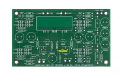
Also measure the voltage at the 33.2k resistor (relative to ground) in the attached image. This voltage is the bias or grid voltage for the Nutube and it should be about 5.2V or so when pot set is at maximum.
I'm having a discrepancy between test points 7 and 8 on a just completed build. The voltage looks to be within a good range on TP7, but TP8 is about 18 V and the trim pot varies it only a volt or two. .........
Post #7,681, you wrote, On the right I measure across R1: 1.44V. Across 332k: .47V.
The 0.47V drop across the 332k load resistor is not compatible with 18V+/- at TP8, because if the power supply voltage was 24V and the voltage drop was 0.47V, T8 should measure 24V-0.47V=23.53V. Alternatively if T8 was 18V then the voltage drop across the 332k resistor should measure 24V-18V=6V.
So please remeasure:
1. Power supply voltage at T3 (relative to ground)
2. Voltage at T8 (relative to ground)
3. Voltage drop across 332k resistor
Also measure the voltage at the 33.2k resistor (relative to ground) in the attached image. This voltage is the bias or grid voltage for the Nutube and it should be about 5.2V or so when pot set is at maximum.
Attachments
Haven't got the eagle's eyes (and patience) some here have... But in a very general way if it would be me I would defo reflow all wires to board connections - they don't look great.
Or at least use your meter to check continuity with the next part...
I let the experts post
Claude
Or at least use your meter to check continuity with the next part...
I let the experts post
Claude
Oh, and +1 on Ben Mah, who - as usual- is making a lot of sense... some measurement seems odd indeed...
@Ben Mah here are the measurements:I didn't see anything that looked bad or wrong in your pictures.
Post #7,681, you wrote, On the right I measure across R1: 1.44V. Across 332k: .47V.
The 0.47V drop across the 332k load resistor is not compatible with 18V+/- at TP8, because if the power supply voltage was 24V and the voltage drop was 0.47V, T8 should measure 24V-0.47V=23.53V. Alternatively if T8 was 18V then the voltage drop across the 332k resistor should measure 24V-18V=6V.
So please remeasure:
1. Power supply voltage at T3 (relative to ground)
2. Voltage at T8 (relative to ground)
3. Voltage drop across 332k resistor
Also measure the voltage at the 33.2k resistor (relative to ground) in the attached image. This voltage is the bias or grid voltage for the Nutube and it should be about 5.2V or so when pot set is at maximum.
1: 22.4V
2: 19.5V
3: .01V
I measured the voltage drop of the 33.2k resistor adjacent to the one you asked about and it reads .18V.
@ClaudeG Continuity is good. I have the pot partially disconnected to flip the board.
@6L6 Thank you! I'm gonna put a magnifier on my magnifier and swap those and check the other 332s. This is the same issue the guy had in the video or blog post I looked at but couldn't find. I'll post back when I complete this.
The eagle eyes of a pilot. Great catch, Jim. 33.2k in place of 332k as load resistor will screw up the voltages.
hi all.
I got a question.. I bought a 600:600 LOT and wished to install them to korg B1.
I wish to do parafeed style so I just bypass the final. 2 resistor and connect directly to output of cap and ground ?
I'm told to add a 470 ohm between output
what does that do?
Thanks
I got a question.. I bought a 600:600 LOT and wished to install them to korg B1.
I wish to do parafeed style so I just bypass the final. 2 resistor and connect directly to output of cap and ground ?
I'm told to add a 470 ohm between output
what does that do?
Thanks
First, thanks to @6L6 @Ben Mah and the others who strained their eyes to no avail, as I did. Upshot, reversed the two 332 family resistors and like magic, all's good. It's running now. The only microphonics I hear happen on on the selector switch. Wouldn't mod anything to isolate the tube. I have the double stick tape peeled and stuck on both sides. The pre will go in a setup where I currently use only a pot for volume control. So I think it will have a different sound. I'll let you know what I think at some point.You can zoom into photos REALLY BIG on an iPad…
🙂 🙂 🙂
Let me point out how I made the mistake. I can't see color codes too well and I do use a magnifier on everything, but since I don't trust my eyes like I trust my ears, I measured all the resistors as 6L6's guide directs. No problem there. Then I make groups and label them with tape. So where's the problem? Just plain picked out of the wrong pile. 🙂
Again, I appreciate the assistance.👍
hi all.
I got a question.. I bought a 600:600 LOT and wished to install them to korg B1.
https://www.diyaudio.com/community/threads/whats-wrong-with-the-kiss-boy.293169/
I have learned to use an ohm meter when stuffing resistors...

As I do, never a wiser word was said from the great man.
Very good advice as usual from Nelson.
Very good advice as usual from Nelson.
Hi experts:
Is there an easy way to add remote volume control to my B1 w/Korg preamp?
I can solder and follow directions, but need basic hand holding (aka 6L6 build guides).
Thanks
Craig in Seattle
Is there an easy way to add remote volume control to my B1 w/Korg preamp?
I can solder and follow directions, but need basic hand holding (aka 6L6 build guides).
Thanks
Craig in Seattle
you need any remote-motorized volume package instead of existing physical one
even cheapest so-called-Alps from Aliexpress will do the job
not saying anything will you get dud of pot itself, that's another issue
whichever option you choose, count on fact that it demands separate PSU
even cheapest so-called-Alps from Aliexpress will do the job
not saying anything will you get dud of pot itself, that's another issue
whichever option you choose, count on fact that it demands separate PSU
- Home
- Amplifiers
- Pass Labs
- B1 with Korg Triode