5mF is not that big
anyway, 20VA Donut is not a Big Spender, that itself can't deliver big surge to caps, whatever their size is
anyway, 20VA Donut is not a Big Spender, that itself can't deliver big surge to caps, whatever their size is
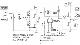
ZMEngrish is the best form of Englishmeans - put 220R gate resistor for output JFet
and , 33pF from tube anode to positive rail (practically across anode resistor)
or from anode to GND
that's that - sorta Papatongue translated to ZMEngrish


means - put 220R gate resistor for output JFet
and , 33pF from tube anode to positive rail (practically across anode resistor)
or from anode to GND
that's that - sorta Papatongue translated to ZMEngrish
Attachments
increasing value of gate stoppers is helping, not decreasing
try 33p (or more) to GND
or even to tube grid
try 33p (or more) to GND
or even to tube grid
So to add 220 onto 1k resistor not swap?increasing value of gate stoppers is helping, not decreasing
try 33p (or more) to GND
or even to tube grid
Again, if possible a drawing such as above for that 33p to ground/grid would be much appreciated 🙏
well, attach here exact schematic of your circuit
I'm sometimes lost which one is actual, using what's published in post #1
whatever value of gate resistor you have, increase it
33pF cap ( or bigger - you must try that) - one end of it to anode pin, other end to closest GND trace/point
if you're not able to understand that, think; if you're again not able to understand that - leave everything aside, proceed once when you have more understanding of circuits and their physical emanation
simple as that - I'm not belittling you in any way, just trying to be realistic; I'm sure that you're ( same as everyone else) good in something else, in which I'm more than clueless
@Zen Mod alright, i've replaced 1k with 2k2, left 33pf across 332k, and added 33pf from anode to ground, and it does seem to lower the hum/hiss. Tomorrow i'll get resistors up to 10k and give it a try with those, to see if that noise is managable to the point that i don't hear it in listening position.
I took the suggestion and finished the project. Board is 2.5"x1.25" and provides a 4-second delay which is ideal for my B1K board. If anyone is interested, the project is at this thread. (final design at post #3)having output cap in preamp, simplest and best way is to simply ground outputs with relay
meaning - relay simply shorting output to GND
I'm fine-tuning my turn-on delay and power loss muting circuit and trying to decide at what supply voltage the circuit becomes unreliable when power is lost. I can set the mute to activate at any voltage with considerable precision but I don't know what voltage best determines when to activate the mute. Anyone know?
Halfway between too little and baseline.
You can decide what "too little" and "baseline" mean for you, perhaps using a variac to create (mains +8%) and (mains -8%), and/or perhaps listening to the output and noticing where it begins to become slightly objectionable or strongly objectionable or unlistenable. At different loudness levels and with different genres of music (full orchestra vs. solo voice etc).
You can decide what "too little" and "baseline" mean for you, perhaps using a variac to create (mains +8%) and (mains -8%), and/or perhaps listening to the output and noticing where it begins to become slightly objectionable or strongly objectionable or unlistenable. At different loudness levels and with different genres of music (full orchestra vs. solo voice etc).
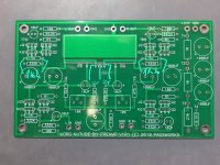
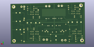
My board is in the garage atm, as i'm remodelling my apartment, and it's on pause trying to get rid of that hum. In the meantime, i'm trying to design a board with 2200uf caps, and mostly because i want it printed in black or purple. Here's whats done so far. If someone notices something off, it would be helpful to write up a comment. Thanks 🙂
Attachments
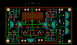
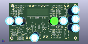
I’d strongly recommend you consider returning that drek to the store and ask for a refund. If you made a quiet one used in the same environment, I can think of few other culprits than the Nutube itself. But of course, I may be wrong. If you can’t prove it is the tube, I imoe won’t expect much willingness to refund a dime.My board is in the garage atm, as i'm remodelling my apartment, and it's on pause trying to get rid of that hum. In the meantime, i'm trying to design a board with 2200uf caps, and mostly because i want it printed in black or purple. Here's whats done so far. If someone notices something off, it would be helpful to write up a comment. Thanks 🙂
regards,
Andy
I'm not giving up 🙂 People have had it dead silent, and first one was silent. Balanced version is always an option too. And finished/tested gerber will be my contribution to people who want 2200 uf caps (16mm width, like this one 647-UHW1H222MHD ), different pcb color, and if they are unable to order one from diystore due to shipping rates if they live far away like myself.
- Home
- Amplifiers
- Pass Labs
- B1 with Korg Triode