You mean 2SK170?Need help - What do I use in place 2sk370 what are current easily purchaseable equivalent.
Use J113, or 2SJ170 (from diyaudiostore.com)
Last edited:

That’s is a economical part thank you very much.You mean 2SK170?
Use J113.
I went into a spin after seen the price for LSK389.
Just remember to order plenty so that you have enough of them to match a specific resistor value, or order a bunch of resistors to achieve the correct current that way 🙂That’s is a economical part thank you very much.
I went into a spin after seen the price for LSK389.
Brainfart, as always. Correct determination is LSK170 from the store 🙂You mean 2SK170?
Use J113, or 2SJ170 (from diyaudiostore.com)
From the early days of my B1K, I have been using a start delay relay to keep the “thump” from going downstream to my amplifier.
Recently I agreed to do a cut-down version of my circuit for another fellow on this thread, and have been re-drawing the circuit to fit on a small board, and it occurred to me to wonder about the way I had configured the output relay in my original design.
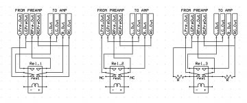
Attached is an image the depicts my original design which I am using now (Rel_1) and two alternate ideas that I came up with after I began to wonder about my original decision.
Rel_1 – the preamp signal is disconnected from the power amp cable center conductor and the center conductor of the cable is shorted directly to the cable’s outer shield ground thus grounding the input of the power amplifier. The grounds remain connected to each other and the preamp signal conductor floats.
Rel_2 – is a simple disconnection of the preamp signal from the poweramp cable center conductor so both preamp and power amp center conductors are floating. The grounds remain connected to each other.
Rel_3 – the preamp signal is disconnected from the cable middle conductor and instead connected to the ground conductor through a resistor, perhaps 20K. The grounds remain connected to each other and the power amplifier cable center conductor floats.
Is there a clear winner of these three options or perhaps yet another configuration that is considered to be best practise?
Recently I agreed to do a cut-down version of my circuit for another fellow on this thread, and have been re-drawing the circuit to fit on a small board, and it occurred to me to wonder about the way I had configured the output relay in my original design.
Attached is an image the depicts my original design which I am using now (Rel_1) and two alternate ideas that I came up with after I began to wonder about my original decision.
Rel_1 – the preamp signal is disconnected from the power amp cable center conductor and the center conductor of the cable is shorted directly to the cable’s outer shield ground thus grounding the input of the power amplifier. The grounds remain connected to each other and the preamp signal conductor floats.
Rel_2 – is a simple disconnection of the preamp signal from the poweramp cable center conductor so both preamp and power amp center conductors are floating. The grounds remain connected to each other.
Rel_3 – the preamp signal is disconnected from the cable middle conductor and instead connected to the ground conductor through a resistor, perhaps 20K. The grounds remain connected to each other and the power amplifier cable center conductor floats.
Is there a clear winner of these three options or perhaps yet another configuration that is considered to be best practise?
Attachments
having output cap in preamp, simplest and best way is to simply ground outputs with relay
meaning - relay simply shorting output to GND
meaning - relay simply shorting output to GND
So if I understand correctly -- 100R is enough load for the B1K to ground continuously and the relay grounds both the B1K and the power amp at the relay without disconnecting the preamp from the power amp? If this circuit were to be used possibly in other preamps -- i.e. treating as a univeral delay circuit -- then would this solution still be best?having output cap in preamp, simplest and best way is to simply ground outputs with relay
meaning - relay simply shorting output to GND
just understand it as short across output RCA
yes, as long there is no significant DC offset ( temporary or not) to deal with, shorting is best way
yes, as long there is no significant DC offset ( temporary or not) to deal with, shorting is best way
Thanks!just understand it as short across output RCA
yes, as long there is no significant DC offset ( temporary or not) to deal with, shorting is best way
Tried mean well rs-25-24, and still the same. Alu case hasn't arrived today so i guess monday to give boxing it a try. In the meantime i will give it a go with pure rca connection to amp this weekend.
As expected. Why not try Papa’s advice? 🙂Tried mean well rs-25-24, and still the same. Alu case hasn't arrived today so i guess monday to give boxing it a try. In the meantime i will give it a go with pure rca connection to amp this weekend.
I ordered this before 🙂 And i think i need to find someone more knowledgeable to translate that to me as in how to do it and where 😅As expected. Why not try Papa’s advice? 🙂
you are in the right place.I ordered this before 🙂 And i think i need to find someone more knowledgeable to translate that to me as in how to do it and where 😅
ZM: You are needed 🙂
"The output at the plate is quite high impedance, which is why we buffer it with a jfet before sending it out into the world. This makes for opportunities for noise picked up from the environment, noise from the load resistor and possibly high frequency oscillation. For the latter you can explore some gate resistance for the jfet or some small capacitance (pf) attaching the plate to somewhere else."
Dis 😁 @Zen Mod
Dis 😁 @Zen Mod
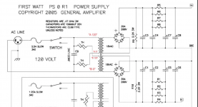
How does one size thermistors for the transformer primary of a PSU?
My B1K is powered via an external PSU which is a 25VA tordial transformer feeding ~5000uF reservoir caps (Pi filtering and regulation after).
I have some SL-15 lying around. Can I put them on the transformer primary like the application attached?
My B1K is powered via an external PSU which is a 25VA tordial transformer feeding ~5000uF reservoir caps (Pi filtering and regulation after).
I have some SL-15 lying around. Can I put them on the transformer primary like the application attached?
Attachments

How does one size thermistors for the transformer primary of a PSU?
My B1K is powered via an external PSU which is a 25VA tordial transformer feeding ~5000uF reservoir caps (Pi filtering and regulation after).
I have some SL-15 lying around. Can I put them on the transformer primary like the application attached?
no need for soft start function of NTC in this case - small mains xformers are not inducing big inrush currents
Even with the big reservoir caps?no need for soft start function of NTC in this case - small mains xformers are not inducing big inrush currents
I guess the circuit as a whole is pulling very little current.
- Home
- Amplifiers
- Pass Labs
- B1 with Korg Triode