Is there a post in this thread with the final schematic diagram and an up to date complete parts list / BOM that matches the NP design PCB's that are being delivered now.
Very soon.
Nice  Thank You Mr.Pass
Do we get not 100R resitors at the outputs with 33.2K on the new boards ?
B1 with Korg Triode
Thank You Mr.PassDo we get not 100R resitors at the outputs with 33.2K on the new boards ?
B1 with Korg Triode
Apart from the output resistor values Soundhappy has mentioned, there also seems to be a 1K resistor on the gate of Q1 output Jfet on the PCB, that is not shown on the new circuit, thanks Nelson.
FYI the diyAudio store now has a small stock of Nutubes to get the ball rolling, with more on the way.
Korg Nutube 6P1 Dual Triode – diyAudio Store
Korg Nutube 6P1 Dual Triode – diyAudio Store
+F 100R's are optionals with specyfic jfet's ?
My error - the 1K was left off the schematic. It is optional in any case, as
the original did not have it, but I recommend it as a pro forma.
Output resistor should be anything you like in excess of 100 ohms.
Thanks Mr. Pass for interesting, easy to build preamplifier.
Superb H2 tool with triodes.
My prototype is near ready for the first voltage tests.
Best regards 🙂
Superb H2 tool with triodes.
My prototype is near ready for the first voltage tests.
Best regards 🙂
Here's some more information.
You will understand that the best way to adjust this circuit is with a
distortion analyzer. Many of you do not have this, but you do have
multimeters.
I just finished testing a small batch of the Xmas boards using matched
2SK370's and drawing from two separate batches of Nutubes.
I mention the matched 2SK70's as important because it is difficult to
accurately measure the Plate voltage of the tube because the impedance
is very high and the ordinary multimeter will load it down, so I used the
DC output of the Fet buffer, and the matching assures that it is close to
actual Plate DC.
The Plate voltage which gives a nulled 2nd harmonic (leaving about .25%
3rd harmonic) averages 11.5V with a spread of about +/- 0.3V.
1% @ 1V 2nd harmonic with the desired positive phase (remember, it
will be negative after you invert the speaker phase) occurs at about
9.4V also with a spread of about +/-0.3V. This is achieved when you turn
the adjustment pot clockwise from the null position.
1% @ 1V negative phase 2nd harmonic is achieved at about 1.1V greater
than the null position, or about 12.6V. This is not not generally the
preferred position, but you want to know where it is in case you want
to play.
In between values give what you would expect, as well as going farther
than these figures. You won't break the circuit with any setting.
The circuit does have a turn-on and turn-off transient, as well as a
DC shift during adjustment. Best to not have the amplifiers running.
Keep in mind that this calibration requires 24 V regulated supply - any
variation will show up as a slightly different setting.
If you have a means of measuring distortion but can't tell the phase
(for example, using a soundcard to make the measurement) then simply
find the lowest distortion point, and then as you turn the pot clockwise
you go into positive phase, or negative phase with counterclockwise.
There is an additional procedure for those not using the matched 2SK
parts which will be posted soon.
There is a small discrepancy between the silk screen and the schematic. The output feedback resistor to the source/gate is 33.2K on the board but 332K on the schematic. I assume it should be 332K.
ANOTHER EDIT: based on build picture posted it is 33.2K
EDIT: I see @soundhappy asks this a few posts back but I do not see clarification
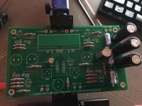
Almost done
Thanks again NP, looking forward to experimenting with the harmonic distortion
.. dB
ANOTHER EDIT: based on build picture posted it is 33.2K
EDIT: I see @soundhappy asks this a few posts back but I do not see clarification
Almost done
Thanks again NP, looking forward to experimenting with the harmonic distortion
.. dB
Last edited:
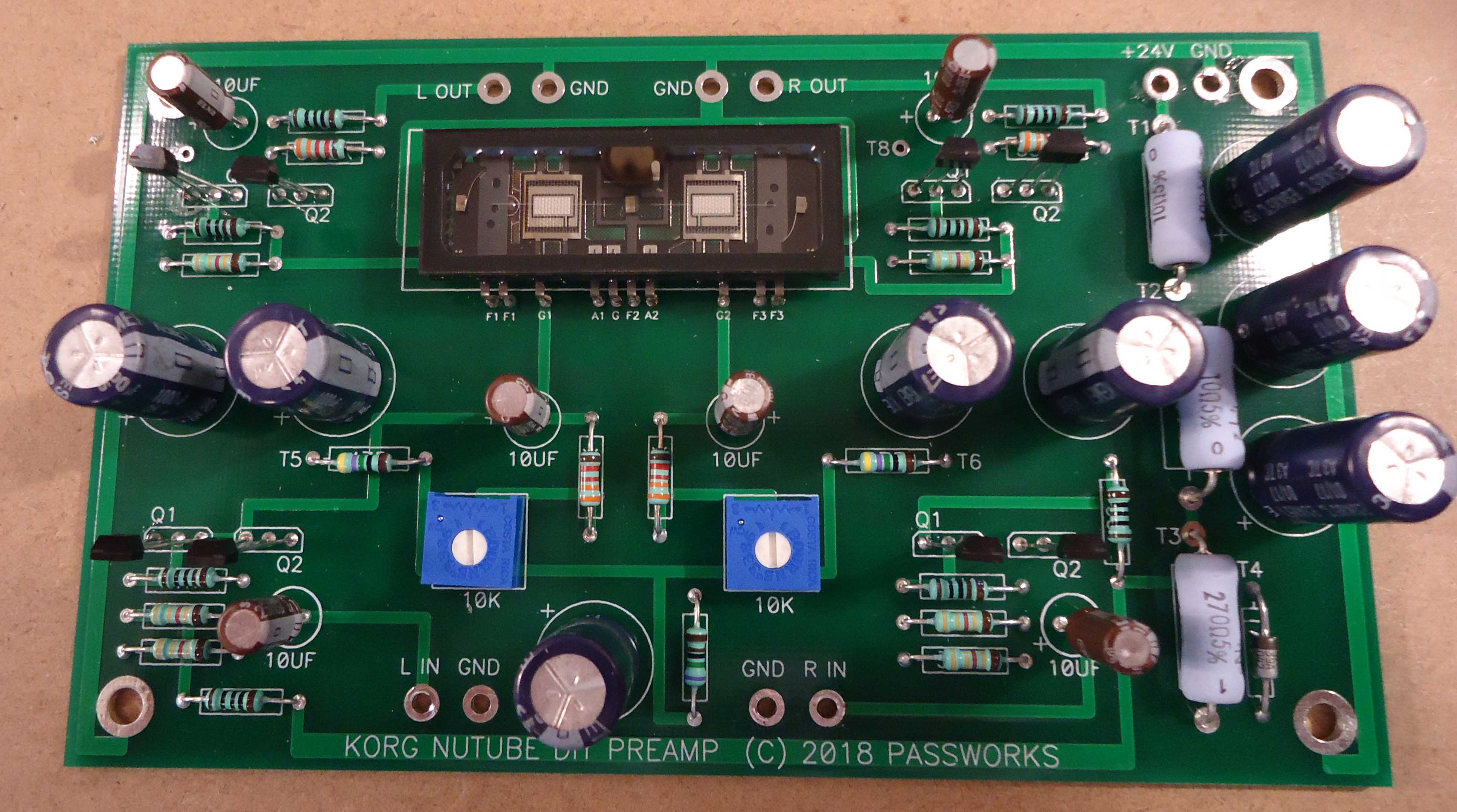
Also hoping for confirmation on correct value, but this picture of the stuffed board shows a 33.2K in that position, consistent with the silkscreen.
For all who want to see the phase of the second harmonic use Diana distortion software, discussed here
DiAna, a software Distortion Analyzer
I used it the last months to measure the k2 phase of F4 beast, DEFSIT, SIT-2, Aleph 3 and, and...
works like glue....!
🙂
DiAna, a software Distortion Analyzer
I used it the last months to measure the k2 phase of F4 beast, DEFSIT, SIT-2, Aleph 3 and, and...
works like glue....!
🙂
There is a small discrepancy between the silk screen and the schematic. The output feedback resistor to the source/gate is 33.2K on the board but 332K on the schematic. I assume it should be 332K.
ANOTHER EDIT: based on build picture posted it is 33.2K
Attached is the schematic. I see that the output resistor to ground is
332K on the schematic and 33.2K on the board.
It really doesn't matter, as this is just a bleeder resistor for the output
cap. You can leave it off if you want, and 33K is not enough of a load
to make a difference. I recall that the boards I built use 33.2K.
Attachments
I'm using a $30 Eiderol DAC, a laptop and Room EQ Wizard (free) running in the RTA mode with "show distortion". Input source is a smart phone running the "Tone Generator" app (again free) set to 1KHz. Preamp output level is set to 1V RMS (or at least as "RMS" as my old Fluke meter will read at that frequency). Starting with the Korg plates on the 'less than half supply' side of things, I found a second harmonic peak over a fairly broad range but a narrower spot within that where the third harmonic was minimized. I like what I hear at that setting. This is with 475K plate resistors. Will be curious to see how the B1 version sets up with the recommended 332K plate resistors.
Last edited:
- Home
- Amplifiers
- Pass Labs
- B1 with Korg Triode