@ Dmy
Schade 50W have 20 dB of gain so Korg preamp is interesting candidate.
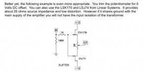
One important parameter is B1 Triode output impedance = 140 to 170 Ohms is nice low but not ideal for this specyfic amp.
Schade need 25 Ohms at the input for the best wide frequency response bandwith.
Perfectly on more buffer 2SJ74/2SK170 stage keep input always at 25 Ohms after that You can try connect all preamps you get.
B1Triode pre is very flexible , trimmer on H3 low distortion position if Schade 50W have lot of H2.
Other candidate imho can be Wayne LineStage BAF2018 this one have very low output impedance few ohms without use of rare vintage jfets. Preamp distortion are H2 second harmonic
so this time Schade 50 W CCS load 0.1R + 0.1R + 0.1R + 0.1R resistances position modification can bring low distortion and third H3.
Avoid too much H2 and keep in equilibre 🙂 Modify sound to Your taste
Schade 50W have 20 dB of gain so Korg preamp is interesting candidate.
One important parameter is B1 Triode output impedance = 140 to 170 Ohms is nice low but not ideal for this specyfic amp.
Schade need 25 Ohms at the input for the best wide frequency response bandwith.
Perfectly on more buffer 2SJ74/2SK170 stage keep input always at 25 Ohms after that You can try connect all preamps you get.
B1Triode pre is very flexible , trimmer on H3 low distortion position if Schade 50W have lot of H2.
Other candidate imho can be Wayne LineStage BAF2018 this one have very low output impedance few ohms without use of rare vintage jfets. Preamp distortion are H2 second harmonic
so this time Schade 50 W CCS load 0.1R + 0.1R + 0.1R + 0.1R resistances position modification can bring low distortion and third H3.
Avoid too much H2 and keep in equilibre 🙂 Modify sound to Your taste
Attachments
Got the board. Yup, definitely an amateur. I soldered all of the resistors I had from the pack. The .pdf cites (2) 100 ohm resistors, which I ordered, making it two 100 ohm resistors short of the actual board, so if anyone orders from the .pdf, order (4) 100 ohm resistors. Soldered the 'Pass Bypass' segment on the leg of one of the caps for the V1R0 version board. 10 ohm resistor are back ordered, 9.1V zener ordered, so I guess I need two 100 ohm resistors.
I am fearing the transistor solder because the pins are so close. Maybe the two sides from the top and the middle lead from the bottom of the board. My solder technique improved as I went along doing the resistors, from weird to reasonably nice, so hopefully I can get the JFETs in without a botch. I tested everything as I went along values, connection points etc.
I will do JFETs last, hoping my solder technique gets less suck-y as I go along further.
For a first DIY, this stuff is harder than it looks until some practice is attained.
Hi, I placed order of kit and Korg in diyaudioStore, but got no email notification on either be accepted, or shipped, is it normal from the store?
Thank you, Soundhappy.
Great Dmy 🙂
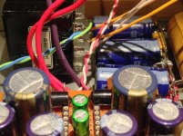
I need finish my Korg prototype " Steampunk " on the perfboard.
All trimmers are multiturns.
P2P and all wiring is a work in progress..after test I can write how is play music together with :
50w Single-Ended BAF2015 Schade Enabled
Passworks pcb are excellent , easy and quick to stuffing
Attachments
Got the board. Yup, definitely an amateur. I soldered all of the resistors I had from the pack....I am fearing the transistor solder because the pins are so close....For a first DIY, this stuff is harder than it looks until some practice is attained.
Relax it's easy
Touch only jfets plastic case with your fingers but not the metal pins.
Body can be charged by static electricity and damage transistors.
Soldering training on some old boards with components can be useful and watch the video's
Basic Soldering Technique
How to Solder Electronics
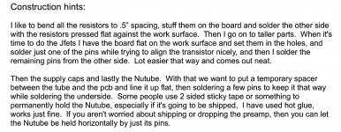
Mr Pass write for us construction hints 🙂 Have a good time
Soundhappy,
Looking forward to hearing from you with your build

Solder wire - Low vs High Quality

Attachments
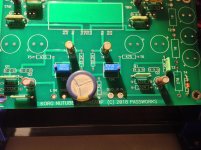
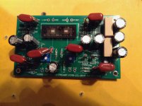
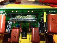
Well, I stuffed the board with everything but the 9.1V zener, which is on order. I used some 10 ohm large resistors that I had for PS, and got two extra 100 ohm resistors from another item, though smaller watt rating.
I have to admit it was scary soldering those transistors. The NuTube was even scarier, but I think????? all is in order. NuTube picture shows surgical gel under tube for microphonics, it can easily be removed and replaced by something else.
Yeah, board looks terrible. 2.25 microfarad polypro caps, strange components, lousy but adequate solder.
After 9.1 zener comes in, its attach the PS and it's all over but the smoke and tears. I give it a 50-50 chance of working.
Attachments
I give it a 50-50 chance of working.
What is Continuity and How to Test for it With a Multimeter
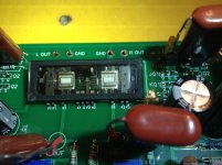
Do Q1 jfets are in good positions ? They are not interchangeable with Q2.
Good luck 🙂
Hi Soundhappy. Do not buy Chinese solder..I find WBT Silver solder the easiest to use.
Cheers
And not buy cheap components , specialy the low quality capacitors
Has anyone tried using something like this for damping the Korg tube?
RTOM MoonGel Damper Pads #1 Dampening Device
RTOM MoonGel Damper Pads #1 Dampening Device
I used the Sigma 11 on my Nutube build and it worked great. The instructions from the AMB site were easy to follow.
How is the noise level from the sigma11?
I should have mentioned I have no way to measure the noise level and that my subjective abilities to judge the noise is not as fined tuned as many others on this forum. So my opinion on the PSU should probably be towards newbies like me that are just trying to build something themselves and want something easy to build.
What I can say is that adding the preamp as a whole to the audio chain does introduce a small level of noise that you must turn up all the way and stick your ear up against the speakers to hear. Where it comes from, the PSU or the B1 circuit, I don't know. My understanding is that the Nutube is a bit noisy when turned up all the way so it could be that.
What I can say is that adding the preamp as a whole to the audio chain does introduce a small level of noise that you must turn up all the way and stick your ear up against the speakers to hear. Where it comes from, the PSU or the B1 circuit, I don't know. My understanding is that the Nutube is a bit noisy when turned up all the way so it could be that.
I have annoyingly sensitive horn speakers that picks up anything from the grid, so I am thinking about getting a power conditioner. My setup is: PC=>USB-cable=>Behringer UCA202 soundinterface=>Optical cable=> Minidsp 4x10HD=> B1=>F5 for the upper two horns and when the RCA cables are disconnected between the B1 and the F5 I have almost no noise. Maybe I can get away with a small power conditioner just for the preamp. Or it could be the minidsp, but I have not found a good 4-way or 5-way crossover yet. Or maybe I was unlucky/unskilled when building the B1. Hopefully this time I get it right.
What is Continuity and How to Test for it With a Multimeter
Do Q1 jfets are in good positions ? They are not interchangeable with Q2.
Good luck 🙂
And not buy cheap components , specialy the low quality capacitors
Thank you, Soundhappy. Yes, I checked everything as I went along, checked component values, checked to see if solder joints were conducting remotely etc. where I could. Fairchild JFETs are in correct positions with R1 resistors on board.
I have been lurking around here long enough to have absorbed most of the basic hygienes, inspected as best I could. However, I also know it is complex enough to blow something somewhere.
However, I also know it is complex enough to blow something somewhere.
I do it on a daily basis. Keeps me on my toes.
Hi everyone:
Has anyone built either the Christmas board of the DIYAudio store board without pots on the input (i.e. buffer only), and could provide sound impressions? I'm thinking of doing this and using my existing preamp.
Thanks;
limits
Has anyone built either the Christmas board of the DIYAudio store board without pots on the input (i.e. buffer only), and could provide sound impressions? I'm thinking of doing this and using my existing preamp.
Thanks;
limits
I have annoyingly sensitive horn speakers that picks up anything from the grid, so I am thinking about getting a power conditioner. My setup is: PC=>USB-cable=>Behringer UCA202 soundinterface=>Optical cable=> Minidsp 4x10HD=> B1=>F5 for the upper two horns and when the RCA cables are disconnected between the B1 and the F5 I have almost no noise. Maybe I can get away with a small power conditioner just for the preamp. Or it could be the minidsp, but I have not found a good 4-way or 5-way crossover yet. Or maybe I was unlucky/unskilled when building the B1. Hopefully this time I get it right.
When I plug in my PC I do get some more noise but not from any other source. The noise is dependent on the CPU load. So when the CPU is grinding away, I can hear it in the speakers. I have no idea what that's all about and I am not sure if it's the PSU, the B1 circuit or what. The PC plugged into my other preamp does not do that. I assumed it was some grounding issue or just the crappy USB coming out of the Intel NUC PC.
- Home
- Amplifiers
- Pass Labs
- B1 with Korg Triode