


Thx 🤗 Yeah, even the box is only 90x158cm. I tried adding holes for signal caps for elcos, but it couldn't be done with keeping both smd and th. On the bright side, those pads are large so trough hole can be soldered on with a little bit of acrobatics 😁
Is there a CAD, .dwg, .dxf or .pdf of the B1 Korg front and back panels? I need to make some mods for Gianluca, but don’t want to start from scratch if it already exists as something i could modify…
Modushop has a specific chassis and for others, they shared with me their 2d, so Gianluca could share with you so you make your mods i guess
their chassis https://modushop.biz/site/index.php?route=product/product&path=242&product_id=828
their chassis https://modushop.biz/site/index.php?route=product/product&path=242&product_id=828
How is it possible that i can buy 50 9.1V zeners and not have one of them measure over 8.38V?? Sorry for the short burst rant…i assume they are within tolerance and should work fine…
There is a pot on that circuit that sets the actual reference voltage, so the tolerance of the
Zener is not consequential.
Zener is not consequential.
Actually I know I’m out of spec. My latest hearing test came back showing that my right ear is a disaster zone, with no frequencies above 11kHz, none below 200 Hz, the in-between down to half of the other ear, and what’s now missing filled with the joyous holiday sounds of raging tinnitus.
And i thought it was the Nutube that was making all that racket.
Left ear is perfect, so i should be able to save some scratch by going full-on mono…
And i thought it was the Nutube that was making all that racket.
Left ear is perfect, so i should be able to save some scratch by going full-on mono…
Ultra noob question here.
Bulit another Korg B1 that uses 2200uF power caps and WIMA poly bypass caps on the underside of things (the bypass caps worked on the last build just fine).
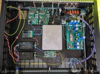
This one's built into a pre with a Salas I-select, some Xkitz crossovers and an ESP P-06 phono pre + P-99 subsonic filter. All power is switchmode (the phono stage gets a silentswitcher, there's a filter on the 24V rail too).
(Without judging my wiring which isn't finished) - just powered it up for a check, when flicking the selector switch the nutube 'flares up' (lights temporarily). Is this normal? Acceptable?
Bulit another Korg B1 that uses 2200uF power caps and WIMA poly bypass caps on the underside of things (the bypass caps worked on the last build just fine).
This one's built into a pre with a Salas I-select, some Xkitz crossovers and an ESP P-06 phono pre + P-99 subsonic filter. All power is switchmode (the phono stage gets a silentswitcher, there's a filter on the 24V rail too).
(Without judging my wiring which isn't finished) - just powered it up for a check, when flicking the selector switch the nutube 'flares up' (lights temporarily). Is this normal? Acceptable?
Attachments
Using larger capacitance can throw smps in protection mode (i've not tried that meanwell, rs works fine with large caps though). Which may be the case here. Just in case, power b1k with just direct 24vdc, no filter, no anything on that supply, just b1k, to avoid additional cap reserves along the way.
Using larger capacitance can throw smps in protection mode (i've not tried that meanwell, rs works fine with large caps though). Which may be the case here. Just in case, power b1k with just direct 24vdc, no filter, no anything on that supply, just b1k, to avoid additional cap reserves along the way.
Thank you - I'll try that tomorrow. I'd taken a look to see if there was a supply rail dip when switching and nothing came up, though response on the multimeter is slow.
Yup, ran into that problem with my B1K which includes three of Mark's PO89ZB filters -- for the 24V and two more for the Meanwell smps +/-15V dc-dc converter in my chassis which adds up to a lot of capacitance when you also include the B1K's filter caps. The symptom was the 'power on' LED would turn on, then off, then back on whenever I applied power to the chassis.Using larger capacitance can throw smps in protection mode (i've not tried that meanwell, rs works fine with large caps though). Which may be the case here. Just in case, power b1k with just direct 24vdc, no filter, no anything on that supply, just b1k, to avoid additional cap reserves along the way.
My solution was to install current-limiting resistors which, when voltages rose adequately, are bypassed by relays. I used 24V mini relays (2 amp contacts) which have a must-operate voltage around 17 volts. I use one relay directly across the 24V line and a second relay for the 15V lines with R11 to compensate for the total 30V across the second relay.
Attachments
Hi forum!
Im new here - I wonder what the trimmer potentiometers are for??? I have the standard kit from the shop - has been a fun build thus far but wander why they are there as there seems to be no identication of adjustments??
Thanks!
Im new here - I wonder what the trimmer potentiometers are for??? I have the standard kit from the shop - has been a fun build thus far but wander why they are there as there seems to be no identication of adjustments??
Thanks!
To allow some leeway to tweak the harmonic content.
"For this circuit the amount and phase of the 2nd harmonic depend on the Plate voltage of each channel of the Nutube which are adjusted by the potentiometers."
"For this circuit the amount and phase of the 2nd harmonic depend on the Plate voltage of each channel of the Nutube which are adjusted by the potentiometers."
thanks for the replies! I have now looked in the manual but i must admit that the level is a bit higher than my abilities. Any advice on where I should connect my voltmeter and adjust for the 10V- it says T7 and T8 but where does the other voltmeter cable need to be connected to? Any ground??. Sorry for the probably naive question....
- Home
- Amplifiers
- Pass Labs
- B1 with Korg Triode