There is nothing wrong with doing things conceptually wrong. New patents may even arise from such a practice 🙂Maybe I'm wrong but I think there is something conceptually wrong with this whole thing. Why would you want to feed this thing with milivolts of signal and then let all the hum and microphonic ringing out?
It should be:
Nutube voltage gain - any ol buffer current gain - potentiometer - low noise buffer (say b1)
Gain is set so as to satisfy the tubes needs/give ideal distortion residuals etc. Noise will be there in the signal no matter where the pot is put. Rest of the circuit I believe is according to Papas recipies taking into account other important factors, dominated by the Nutube I should think.
The extra buffer after the tube is to take control over the output impedance, if I remember correctly (not time right now to double check schem).
Regards.
Andy
Last edited:

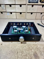
Opened my B1K up yesterday for one more mod (I think I’m done now….). Replaced the stock Alps 50K volume control with the new Academy Audio VCX muse chip based volume control.
https://www.academyaudio.com/product-page/vcx-hi-end-muses-micro-volume-control
Not shown but the VCX has a display module for visual indication of its many functions. The display is required for the control to work. Still deciding if I will add the display somehow or bury it in the enclosure.
The new VCX design is pretty slick, I’ve already paired the unit with an old Appple TV remote.
Also checked bias after running my B1K fir a few months and was happy to find both test points sitting at 9.5 V still.
Attachments

One is all you need.I am planning to use these rubber vibration insulators instead of the brass standoffs. This means that i will loose the groundpoints in every corner.
Does it matter, is the one soldered groundpoint all i really need?

I’ve been designing a relay-based delayed startup connect and immediate output disconnect for the B1K and the design is working fine at 24V supply. I got to thinking that I could add just a little more code to make this a universal design that would operate at any supply voltage. To do this I would sample the stabilized power supply voltage at startup and store it as a reference to decide when to disconnect the output relay when supply voltage starts to drop.
Using this method, the disconnect voltage would be a calculated percentage of the steady-state supply voltage and it would work exactly the same at any voltage up to some maximum, say 30V (based on the use of 35V electrolytics on the board).
What I’m not sure about is what percentage I should use for this purpose. My WAG is maybe 80% but that’s a guess without knowledge of real-world circuit behavior so I’m asking for better-informed advice. Anyone have any recommendations?
Attachments

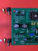
I just want to suggest a cure for the ringing, microphonic of the nutube. Use it as much a you can. I thought I had a problem on my hands after completing the kit. It got me yelled at by a monster that lives in my house. Now, I just noticed, it wont ring even with a pounding from EDM and a nearby subwoofer. That's after a bunch of use. Great news.
I'd feel comfortable using a tighter threshold for a regulated supply, than for an unregulated supply. Something like (Nominal - 15%) for regulated supplies, but (Nominal - 25%) for unregulated. With an unregulated supply you have to plan for AC mains sag and output ripple, especially the troughs of the ripple waveform.I’ve been designing a relay-based delayed startup connect and immediate output disconnect ... the disconnect voltage would be a calculated percentage of the steady-state supply voltage ... What I’m not sure about is what percentage I should use for this purpose. My WAG is maybe 80% but that’s a guess ... Anyone have any recommendations?
I had not considered that difference between regulated and unregulated. I'll set it up for 25% and that should be OK for both possibilities. Thanks for that insight!I'd feel comfortable using a tighter threshold for a regulated supply, than for an unregulated supply. Something like (Nominal - 15%) for regulated supplies, but (Nominal - 25%) for unregulated. With an unregulated supply you have to plan for AC mains sag and output ripple, especially the troughs of the ripple waveform.
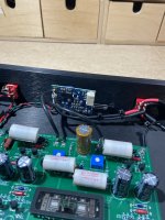
Hey, diyAudio, I don't know if it's already been commented on, but please don't use that Bell Telephone wire in the kits for hookup. It's hard-drawn, and it work hardens and breaks easily, especially if you strip it with a knife and nick it. The insulation is made for IDC, not soldering, and it melts and causes shorts between the twisted pairs and anything else it's resting against. I used this stuff a lot in high school when I couldn't afford anything better, and it was a constant source of problems. I just spent a couple of hours tracking down a short in the power caused by melted insulation. Thanks.
Hey, diyAudio, I don't know if it's already been commented on, but please don't use that Bell Telephone wire in the kits for hookup. It's hard-drawn, and it work hardens and breaks easily, especially if you strip it with a knife and nick it. The insulation is made for IDC, not soldering, and it melts and causes shorts between the twisted pairs and anything else it's resting against. I used this stuff a lot in high school when I couldn't afford anything better, and it was a constant source of problems. I just spent a couple of hours tracking down a short in the power caused by melted insulation. Thanks.
As i understand it, the supplied wire is CAT6 twisted pairs. Regular LAN-cable.
Coper is copper is copper?🙂
Do not overheat the circuitboard, the connectors or the cable insulation. If you are shorting the twisted pairs = WAY to much heat for FAR to long.🙂
But then of course, silicone or teflon insulation can take MUCH more heat.
Ethernet cable was originally coaxial. Balun technology was developed to use cheaper telephone twisted pair cables, so CAT cable is still essentially the same.
Copper is not always the same. Read about annealing and work hardening. Stranded wire is electronics industry standard for interconnects because it handles being bent better than solid conductor. Especially in DIY projects, you need to be able to bend the wires to make changes and move things around without breaking connections.
If you're soldering to a lug that is acting as a heat sink, you need to use more heat. If the insulation fails when you do that, then it's a poor choice. Especially when it fails in hidden places like this.
Attachments
![DSCF0726[1].JPG](/community/data/attachments/993/993613-308219cc281a2ced3019b2c59dc91293.jpg?hash=MIIZzCgaLO)
Greenhorn soldering - one must use non melting isolated wire (PTFE, whatever)
proper soldering - one can use whatever is chosen
proper soldering - one can use whatever is chosen
Ethernet cable was originally coaxial. Balun technology was developed to use cheaper telephone twisted pair cables, so CAT cable is still essentially the same.
Copper is not always the same. Read about annealing and work hardening. Stranded wire is electronics industry standard for interconnects because it handles being bent better than solid conductor. Especially in DIY projects, you need to be able to bend the wires to make changes and move things around without breaking connections.
If you're soldering to a lug that is acting as a heat sink, you need to use more heat. If the insulation fails when you do that, then it's a poor choice. Especially when it fails in hidden places like this.
Okey, i see.
Well. This is how i do it: Never dwell longer than 2-3 seconds, 340C on the soldering iron.
Attachments

Okey, i understand what you mean. And it is a very good advise! But i like to see all the fine and shiny solder jobs. 🙂@JeyDee , in that pictured example, I definitely would put shrink tubing on the center connection, and perhaps on the ground as well.
I'm not careful enough to always avoid shorting things like that. 🙄
Kind regards,
Drew
Thats just simply how i roll 🙂🎸
You need to post some pics of that AJ. That’ll illustrate your point and style properlyOkey, i understand what you mean. And it is a very good advise! But i like to see all the fine and shiny solder jobs. 🙂
Thats just simply how i roll 🙂🎸

Thanks for the tip, I've only been soldering for 60 years.Greenhorn soldering - one must use non melting isolated wire (PTFE, whatever)
proper soldering - one can use whatever is chosen
MZM’s definition of greenhorn is very wideThanks for the tip, I've only been soldering for 60 years.

Thanks for the tip, I've only been soldering for 60 years.
what I wrote is true, general and not quote of you/your post
- Home
- Amplifiers
- Pass Labs
- B1 with Korg Triode