OK, I'll grant it's possible to successfully build a kit with this wire. Obviously lots of people have, and I will, too. But I built my first Heathkit in the 2nd grade, I've made a lot of solder joints since then, and the most troublesome hookup wire in all that time has been this kind. It simply was never designed for that purpose, and it can and does cause problems that wouldn't otherwise have occurred. And if diyAudio wants to reduce the problems customers have in building their kits then my experience says that they shouldn't use it. 'Nuff said.what I wrote is true, general and not quote of you/your post
Then you should have known to heat the lug first, use tin drop on tip to transfer heat better, and then bring wire and solder, easy peasy. No burnt isolation of any kind, three missisipy contact 🙂Thanks for the tip, I've only been soldering for 60 years.

I havent been soldering for 60 years and have had no problems with that wire. Used it in numerous amps and preamps without issue. Just have to pay attention, move deliberately, only contact what you are connecting.
I just put the NuTube preamp back into service, and it still sounds amazing pushing my F4.
I just put the NuTube preamp back into service, and it still sounds amazing pushing my F4.
Hey there hifi dudes!🤗
At last! I have been playing the B1 as a pure preamp directly from vinyl to Twin Aleph J:s and…
…also as a triode middle man: no gain. From the digital sources to the Marantz surround preamp. B1 between the Marantz and the main stereo channel Twin Aleph J:s
For six hours straight🥰
The other surround channel speakers are eating power from them fairly delicious, pretty cool running A/B 3x200W + 2x200W Classic Rotel amps 👻
Well, well, well. So??? 🙂Okey. Long story short: You simply have got to love the juicy, lush, massive, golden sweet aura this triode preamp adds to every thinkable musical experience. So far…
👊🙂🎸
What? Golden sound?? Well. You will have got to simply Crankit Up🙂👍
https://tidal.com/track/634657
So im wondering if i damaged my triode. When soldering everything i was really careful and tried to think of everything. The last thing i did was to connect the outputs and start up the amp. When measuring t7 everything was dandy, but t8 went up and down in voltage. tried to leave it for 15 so min hoping it would settle down (ive biult the whammy and dont know so much about amps), when i came back to measure still same problem. I disconnected everything and went on to check everything out to see if i made a misstake somewhere. Well i had forgotten to cut the cables for the output so the were shorted against the chassi. I then cut them and started up the amp again. Ok the left channel, stable and nice. The right channel (T8) had a voltage about 3 and when maxing the potentiometer it was only 4.0 to 4.8 jumping up and down. So ive checked and doublechecked my soldering my placement of the resistors and if anything is burnt. Nothing can be found. So is it possible i damged anything? like maybe the korg or a capacitor or even one of the transistors? I dont know where to begin looking and how to go about.
Any help would be appreciated.
Any help would be appreciated.
I am not sure what you mean by "cut the cables for the output".
Please take clear and focused pictures of both sides of the board.
But before doing that, please measure the voltage drop across the resistors marked and also at T5, T6.
Also look closely and compare the resistors on the right channel to the corresponding resistors on the left channel to check for discrepancies.
Attachments
Blown Channel
A few days ago, for some reason (brain fog caused by alignment of planets?), I started to fiddle with a properly measuring and functioning B1 with Korg Nutube DIY Preamp (from the store) which I built a few years ago. Long story short, I decided to read the current running through the 475R resistor at T5, switched my DMM to read mA (yes, I know) , touched either side of the resistor with the probes and poof, the channel is blown. One side of the Nutube stops glowing and music stops on that channel. I measure some voltages at the test points and across R1, which I do not write down, and immediately decide that I have blown a channel on the Nutube triode. I proceed to desolder it with the intention of replacing it.
Then this morning, I remember that I really have no idea what I am doing, so maybe I should reach out and ask those who do know to help me to troubleshoot the situation and determine whether the Nutube is actually blown; or maybe it is something else.
Right now, the preamp board is intact and complete except with the Nutube removed. I read some posts on this thread which seemed related (starting at#2411) but it was unclear to me how to proceed with the triode no longer in place.
Thanks in advance for any suggestions.
The 475R resistor sets the voltage to the Nutube filament. It sounds like you shorted the resistor and sent too much voltage to the filament and toasted it.
So if it was working before but not working now, the Nutube filament is gone. I don't think anything else would be damaged.
So if it was working before but not working now, the Nutube filament is gone. I don't think anything else would be damaged.
Ill try do do it when im home but i meant by cutting the end of the cables that i soldered to the board. They should have been cut, they were a little to long. Instead they got shorted against the chassi
That's what I guessed as well. Thanks.The 475R resistor sets the voltage to the Nutube filament. It sounds like you shorted the resistor and sent too much voltage to the filament and toasted it.
So if it was working before but not working now, the Nutube filament is gone. I don't think anything else would be damaged.
When measuring voltage drop i just measure voltage by connecting black from dmm to ground and red to each side of resistor right? And then compare voltage to see how much the voltage drop is?I am not sure what you mean by "cut the cables for the output".
Please take clear and focused pictures of both sides of the board.
But before doing that, please measure the voltage drop across the resistors marked and also at T5, T6.
Also look closely and compare the resistors on the right channel to the corresponding resistors on the left channel to check for discrepancies.
To measure the voltage drop across a resistor place the black probe on one side of the resistor and the red probe on the other side of the resistor. The voltage shown on the meter is the voltage drop across the resistor. No calculation needed. Your way will also work but it takes two measurements and a calculation.
For the voltage at T5 and T6, red probe at T5 and black probe at ground, repeat at T6.
For the voltage at T5 and T6, red probe at T5 and black probe at ground, repeat at T6.
I finished the start delay & manual Mute pcb project using the power supply nominal voltage minus 25% for muting as suggested by Mark, and the board works for any voltage between 10 volts and 30 volts supply. If anyone is interested in adding a delay & Mute circuit to their B1K, all the needed info is here and I think the iteration at post 7 is the final one.I'd feel comfortable using a tighter threshold for a regulated supply, than for an unregulated supply. Something like (Nominal - 15%) for regulated supplies, but (Nominal - 25%) for unregulated. With an unregulated supply you have to plan for AC mains sag and output ripple, especially the troughs of the ripple waveform.
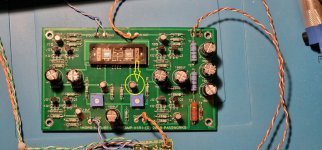
So ive measured and taken some pictures. The underside is a little dirty because my attempts to clean it before the picture was really bad. Im gonna se if i can buy som solderflux cleaner.
Measurements:
R1= L channel (good channel) 1.4072V, R channel (bad channel) 1.3686V
332K= L channel (good channel)1.383V, R channel (bad channel) 16.660V - 16.705V (jumping around)
T5 = 0.6270V
T6= 0.6739V
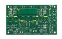
![20220911_115835[1].jpg](https://www.diyaudio.com/community/data/attachments/997/997614-1de4fb3cc550a5e7b0e98e1f35689a48.jpg?hash=HeT7PMVQpe "20220911_115835[1].jpg")
![20220911_120019[1].jpg](https://www.diyaudio.com/community/data/attachments/997/997613-ae9499d169306a19809ba8fc98d3e410.jpg?hash=rpSZ0Wkwah "20220911_120019[1].jpg")
Measurements:
R1= L channel (good channel) 1.4072V, R channel (bad channel) 1.3686V
332K= L channel (good channel)1.383V, R channel (bad channel) 16.660V - 16.705V (jumping around)
T5 = 0.6270V
T6= 0.6739V
So I've measured and taken some pictures. The underside is a little dirty because my attempts to clean it before the picture was really bad. Im gonna se if i can buy som solderflux cleaner.
Cleaning with rubbing alcohol and a soft bristle toothbrush then patting dry with an absorbent cloth works well for me.
Dammit. So bad thank you ill test changingCapacitor placed incorrectly - polarity reversed:
By the way, the 1.383V is probably 13.83V. Must be a typo, or you misread your meter. Not to worry. 🙂................
Measurements:
R1= L channel (good channel) 1.4072V, R channel (bad channel) 1.3686V
332K= L channel (good channel)1.383V, R channel (bad channel) 16.660V - 16.705V (jumping around)
T5 = 0.6270V
T6= 0.6739V
- Home
- Amplifiers
- Pass Labs
- B1 with Korg Triode