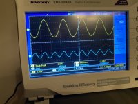
Few pics. Disregard my 18V6 advice. It oscillates at that voltage. I did not succeed in adjusting for a clean neg 2nd harmonic, with nice sines. The cleanest sines are @ stock 9V5, positive phase 2nd harmonic. Thank you, Papa 🙂 Reference is reference.
old school equip up working for the first time. For me, an achievement.
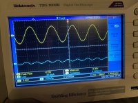
notice the 3rd harmonic adjustment, @ approx 13V7. It is possible to adjust distortion even lower, but not with a clean sine.
then the happy positive phase 2nd harmonic, meaning negative after inverting @ speaker posts.

old school equip up working for the first time. For me, an achievement.
notice the 3rd harmonic adjustment, @ approx 13V7. It is possible to adjust distortion even lower, but not with a clean sine.
then the happy positive phase 2nd harmonic, meaning negative after inverting @ speaker posts.
Attachments

Well done Mikerodrig27 and thanks for sharing the comparo
Enjoy music very much
Claude
Enjoy music very much
Claude
Audio tested it today, and it is sweet! It literally was layed on the desk on top of paper towel, and no microphonics. Now to cnc mill down the case. Such sweet device, kudos 😊
I’ll try to explain it in greenhorn terms. Easy, since I am one to begin with.I'm on a learning curve with oscilloscopes. I have a Hantek desktop 2 channel scope of the same fundamental form-factor as the Tektronix.
What's the basic concept to set it up to show the primary signal and the second harmonic as I see there?
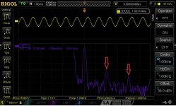
The chain starts with the HP signalgen. It sends a 1khz sinewave to the preamp inputs. In this specific example, the output is 2Vrms (signalgen is a bit unstable, unsure if it actually sent out 2V).
Then I set the preamp, using the pot, to approx 1VAC output (according to scope it seems I didn’t get this quite right). I connect the preamp output to one of the scopes inputs.
then I tap the preamp output once again, this time to the HP334A distortion analyzer. I adjust the analyzer to the fundamental signal, and then use it to filter out «everything» but the distortion residual waveform.
I send this residual to the other input of the scope. Then I adjust the scope so it shows the two signals as depicted.
I spent some time learning how to do this. Also, a functioning 334A in my area was hard to find. A former employee of Electrocompaniet sold it to me cheap. I consider myself lucky 🙂 Also, this means I don’t need to invest in computer hardware iot find out these things (e.e reconfirm Papa’s design) iow, completely useless
 . I don’t own a PC, so a lot of the software is out of reach anyways.
anyways, point is there are easier ways to do this, I am told. And cheaper too. Dunno if they will show residual the same way tho.
i just wanted to do this the old school way.
You can use the scopes FFT to show the harmonic spectra too. And you will know the phase of the distortion in most of Papa’s construction. And from there adjust amount. But, it will be difficult to confirm sinewave shapes for fine tuning. There are ways to do this, tho, using just a scope. Or so I have been told. Haven’t gotten there yet 🙂
Edit: I think the 3rd harmonic pic might actually be the 2nd null point. Wil remeasure. damn greenhorns!
🙂
regards,
Andy
Last edited:
Thank you!
Ah, so the second channel has been "filtered" by a distortion analyzer. I thought maybe some wizardry on the scope itself was doing it.
Which, as you say, is probably possible but... when my college math went from calculus to differential equations, I didn't quite make the cut. Did you know you can't learn a semester of differential equations the night before the final? It's true.
This hobby has forced me to learn and re-learn a lot, and taught me patience. When the time comes that I need it, I'll plod on through.
In my case. Differential equations can never be learned no matter whatThank you!
Ah, so the second channel has been "filtered" by a distortion analyzer. I thought maybe some wizardry on the scope itself was doing it.
Which, as you say, is probably possible but... when my college math went from calculus to differential equations, I didn't quite make the cut. Did you know you can't learn a semester of differential equations the night before the final? It's true.
This hobby has forced me to learn and re-learn a lot, and taught me patience. When the time comes that I need it, I'll plod on through.
I also learn all the time in this hobby. Looking at those pics again, it looks as if the low distortion pic contains pure sine neg 2hd. Will check again, and test wrt the exact voltage I had going at that time. Maybe it will sound good 🙂 learning, goofing, listening, learning some mo’.
No issues with microphonics with my build yet. That said I like to overbuild, overdesign and overthink 🙂
Anyone tried weather stripping inside the chassis as a form of isolation to help with vibration and microphoncs?
Seems like a cheaper option than Dynamat (also easier to get).
Anyone tried weather stripping inside the chassis as a form of isolation to help with vibration and microphoncs?
Seems like a cheaper option than Dynamat (also easier to get).
I put a little piece of double stick weather stripping between the PCB and the bottom of the Nutube. I think I remember reading something about not covering the circle part on the bottom so I was careful not to cover it. When music is playing fairly loud, the ringing will still happen. However, it isn't loud and quickly dies off when the music stops. It isn't loud enough to hear over the music. At normal volumes, it doesn't ring at all. This is with the chassis open as well.
I built a Korg B1 last year with stock parts and I have been reasonably happy with it but the itch to upgrade is upon me. I've read hundreds of posts on upgrading the caps from ClaudeG's work starting around #2610 and going forward into the 5000's and then the stuff that has been posted in the past couple of months. I wanted to summarize my conclusions and see if anybody has any comments from their experience about what does or doesn't work or suggestions about what I could do better.
Capacitors closest to inputs 0.33uF
Capacitors closest to the tube 1 uF
Capacitors closest to the outputs 3.3 to 4.7 uF
I haven't actually read anything justifying those particular values but they seem to be the most common. Any input on that would be welcome.
Quality of capacitors seems to range from Cornell Dubilier 940C's on the low end ranging all the way up to Mundorf Supremes on the high end. I'm thinking either Cornell Dubilier 940C or Jantzen Superior Z-Cap although a part of me wants to splurge on Auricap XO's which look very nice. I haven't read anything about people comparing the higher end capacitors.
Power Supply caps upgraded to 2200 uF
I haven't read anything about the two 1000uF caps that are close to the signal path. Anybody have any comments on that?
Thanks for the input.
Paul
Claud's cap values were calculated with a decent safety factor. If too low, they will act as a high pass filter.
My only advice is to try to stick with the smallest of the cap type that you are taking an interest in. If you have the option for say a 275v cap vs a 600v cap, use the 275. The 275v should be a lot smaller. the spacing is pretty tight and using long wire leads to attach the caps can also be problematic
The voltages are pretty low in this amp.
What have people used for linear power supplies?
I have a 35VA 22V transformer that I was going to use along with a CRC filter and a simple LM317 regulation setup.
Reading this thread is doesnt seem like upgrading the power supply from SMPS to linear makes a huge difference so I'm inclined to not throw big bucks (and time) at the power supply design.
Gaz's single rail power supply is a CRCRC. Decent board although I think a couple of the parts may be going obsolete. Also, the transformer is on the board. Maybe he has something else that would fit the bill better.
Glass-Ware's kit looks nice and would make it so that you could use your transformer to save a few bucks. It isn't a CRC filter, only an RC but I can attest to the quality of Glass-ware's boards, instructions etc. The PCB boards are impressively thick. I used their bipolar supply.
https://glass-ware.stores.yahoo.net/lvregulatorkit.html
The regular heatsink on the power supply for my korg amp is only 4-5 degrees celsius above ambient. It is nice to know that you would have the power supply handy for other projects like the Whammy etc. A nice puzzle piece to fit here and there. Also, there are only a couple parts to change if you want to alter the voltage for something different. I don't think it will make too noticeable of a difference. I was switching between a the stock wall wart switching supply and Gaz's. My audio memory didn't notice a difference. Maybe if I could flip a switch...
Last edited:
Hi Paul,
Quickly for once... in hope it helps
If you read my posts then you will find the answer to the caps values. Key words are high pass filter with the following impedance / resistance, these values where calculated for Fc = 5Hz or so. Please read all my posts on that, as it is often not understood that this resulting filter is not working as a brick: Fc results already to -3dB and of course there is still some minor loss even at 20Hz. Fc has been chosen low in order not to degrade noticeably performance at 20Hz. Now, I do realise most people probably don't have LS that can reproduce without big loss frequencies under 30Hz, so that might not be of interest to them. But it all adds up and my LS have in y room Fc = 25Hz, and I listen to classic, so I care.
The main discussion is in fact about the 3rd cap (the 1st and 2nd in the signal path are no brainer as not expensive and small). That one has been chosen indeed conservatively, as it solely depends on YOUR resulting Fc, and in that particular case it is determined by the said cap's value and the input impedance of YOUR power amp. Something I can't know. All already explained and what to do to calculate YOUR value, several times in fact... have a good read.
Regarding 'Quality of capacitors seems to range from Cornell Dubilier 940C's on the low end ranging', I have to disagree here. It is not because a cap doesn't cost an arm that it is less worth than the ones that do. I am not sure - other than colorations from bad boutique caps- that one can really hear any improvement over the 940C regardless the type of cap they fit: the CDs are VG, regardless price. Last but not least, they are IMHO a great upgrade to the B1K (but you know my POV already 🙂), but you have also to understand that once these are fitted the next bottleneck is probably the colouration and limitations of the Korg itself... which are all the beauty of this preamp! In short: re caps, get the 940Cs and leave it there, that would be my advice.
Good luck and let us know your findings
Claude
I believe this is the primary post of yours that you are referring to although there are certainly other posts you made about your rationale in choosing those values. https://www.diyaudio.com/community/threads/b1-with-korg-triode.313612/post-5838152Hi Paul,
Quickly for once... in hope it helps
If you read my posts then you will find the answer to the caps values. Key words are high pass filter with the following impedance / resistance, these values where calculated for Fc = 5Hz or so. Please read all my posts on that, as it is often not understood that this resulting filter is not working as a brick: Fc results already to -3dB and of course there is still some minor loss even at 20Hz. Fc has been chosen low in order not to degrade noticeably performance at 20Hz. Now, I do realise most people probably don't have LS that can reproduce without big loss frequencies under 30Hz, so that might not be of interest to them. But it all adds up and my LS have in y room Fc = 25Hz, and I listen to classic, so I care.
The main discussion is in fact about the 3rd cap (the 1st and 2nd in the signal path are no brainer as not expensive and small). That one has been chosen indeed conservatively, as it solely depends on YOUR resulting Fc, and in that particular case it is determined by the said cap's value and the input impedance of YOUR power amp. Something I can't know. All already explained and what to do to calculate YOUR value, several times in fact... have a good read.
Regarding 'Quality of capacitors seems to range from Cornell Dubilier 940C's on the low end ranging', I have to disagree here. It is not because a cap doesn't cost an arm that it is less worth than the ones that do. I am not sure - other than colorations from bad boutique caps- that one can really hear any improvement over the 940C regardless the type of cap they fit: the CDs are VG, regardless price. Last but not least, they are IMHO a great upgrade to the B1K (but you know my POV already 🙂), but you have also to understand that once these are fitted the next bottleneck is probably the colouration and limitations of the Korg itself... which are all the beauty of this preamp! In short: re caps, get the 940Cs and leave it there, that would be my advice.
Good luck and let us know your findings
Claude
And I agree with your argument that "no cap in the signal path, [is best] but that is impossible for this pre as there are voltage differences between the stages, so DC blocking caps are absolutely mandatory" and I understand the argument for tailoring the 3rd cap to a safe value for the input impedance for your power amp.
But I guess I don't recall reading or seeing a reason for choosing the .22uF and 1 uF values other than a reference to "ZM’s wise and safe values" and I wasn't able to find that post by him. Your premise seemed to be the least possible capacitance would be the best value but I wonder if that is true or if anybody has tested that? I'm especially curious about that since there is a post somewhere by Papa saying 1uF would be the lowest values he would consider using.
I confess that I don't understand the underlying principles of all this thus by questions.
On a completely different note, is inverting the phase at the DAC the same as inverting phase at the speakers by reversing the + - connections?
Thanks.
.....A former employee of Electrocompaniet sold it to me cheap. I consider myself lucky 🙂 ........
now, you're either smart, or damn lucky - you didn't bought Electrocompaniet
Hello World...
I am a DIY audio neophyte looking for some help with a stock B1 build and hope that I am in the right place. I have been searching the thread but may not know enough to construct the right search string. If I am in the wrong forum please disregard.
Having completed a pair of mono Ampcamps, I decided to step it up and increase my DIY-Fu just a bit with a pre-amp build. I am at the one yard line but get no sound so figure that something is amiss (is there a DUH emoji?). T1-T4 provide the appropriate measurements but there is 0 voltage at T7 and T8. My tube lights up with the expected groovy blue hue. The power supply test during the build was also in line with expectations.
I reviewed all connection points prior to powering on and while comfortable with my build, there is obviously something that I missed. I did employ Pete Millett's NuTube anti-vibration mount though that seemed pretty straight forward. I don't have any visible solder bridges there.
I'm happy to provide photos if you can tell me what you want to see.
But I did. I got the whole company for 200 greeniesnow, you're either smart, or damn lucky - you didn't bought Electrocompaniet

- Home
- Amplifiers
- Pass Labs
- B1 with Korg Triode