Thanks! Nice looking buildChrisM91, I used these to mount the board -
iFlight 12PCS M3X7+4.5 Anti-Vibration Fixed Screws Mounting Hardware Spacer Standoff RC Screws kit with 12PCS M3 Nylon Hex Nut for Naze32 CC3D F3 F4 Flight Controller FPV Racer -
Still in stock on the site that will not be named.
I also used Pete Millett's NuTube mount and have had zero microphonic issues.
Installed slightly larger PS caps with a little effort. Photos a few pages back.
I was going to ask if the Pete Millett mounting fit in the diyaudio store chassis but looking at your build pics I think I've cleared that up!
Did the stock PCB mounting holes work with those standoffs?
I'm looking for some troubleshooting suggestions. My B1K build turns on, triode is a nice blue/green, and all the voltages at T1-8 check out, but I get no sound from either input. I used Cinco's wiring diagram (#5,922) and even has his generous gander and suggestions on the wiring and testing. So far things all check out. Grounds all check out from the inputs to the board, signal showing appropriate resistance when referenced from GND (47.3K ohms Left/A, 46.3K ohms Right/B) at max volume, and (0.9 ohms (A) and 0.7 ohms (B)) at min volume.
Not sure if it's useful but when reading across the board, without power, L IN to L OUT is 33.28K ohms. Measuring L IN to R IN varies with volume. 0.0 to 93.5K ohms.
This is only my second build, the first was a (successful) ACA, so please speak slowly ;-)
Thank you.


Not sure if it's useful but when reading across the board, without power, L IN to L OUT is 33.28K ohms. Measuring L IN to R IN varies with volume. 0.0 to 93.5K ohms.
This is only my second build, the first was a (successful) ACA, so please speak slowly ;-)
Thank you.
 Best regards
As Soundhappy said, reflow joints that look imperfect.
If all of the voltage at the test points are correct, it may be that the wiring from inputs to selector switch to board and from board to outputs has a error somewhere.
Looking at the diagram that you referenced, it looks confusing and not what I would consider the optimum routing. I see that the Right channel Input 2 Ground from the Input 2 RCA goes to the selector switch, then goes to the Right channel Output 2 RCA Ground, then goes to the preamp board Ground. Likewise, the same for the Left channel.
Instead, the Ground wires from both Right channel inputs should bundle with the Right channel signal wire coming out of the selector switch and continue together twisted to the preamp board Ground. As for the Output, only one Ground wire and signal wire from the preamp board Output should go to the Output RCA. The same wiring for the Left channel.
An alternate is to merge the right Input 1 and Input 2 Ground wires at the selector switch and then continue one Right channel Ground wire with the selected Right channel Input signal wire together to the preamp board.
An overall picture of the preamp showing the inputs, outputs, switches, board, etc would be helpful in trouble shooting.
Last edited:
After looking at the diagram again I am less confused. I now realize that the six compartment box is the volume control. I had confused it with the preamp board. However what I previously said about the Ground wiring still holds. From the selector switch, the Ground from the two Right Inputs should stay with the Right signal output and proceed to the volume control input. The grounds connect to the ground point of the volume control. As mentioned previously the grounds of Right inputs 1 and 2 can be combined at the selector switch and then the single wire can be twisted with the signal wire and continue to the volume control. At the volume control the signal output wire and ground wire continue together to the preamp board.
The Input Ground wires do not need to go to the preamp board from the RCAs and then to the volume control.
Again pictures showing the overall view of the preamp would be most helpful.
The Input Ground wires do not need to go to the preamp board from the RCAs and then to the volume control.
Again pictures showing the overall view of the preamp would be most helpful.
Last edited:
I’d like to add a Academy Audio VCU volume control eventually. It requires a bipolar supply.
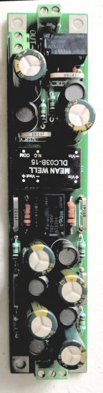
I found a populated PSU PCB lying around from a project that I never got to:
https://www.tindie.com/products/skrodahl/muffsy-hifi-dual-power-supply-v4-kit/
The PSU is a half wave rectifier that create a + and - supply using a PI filter and then a LM337/LM317 for regulation.
Could the B1K run off the half wave regulated supply? It would be 24V off course.
After some further thought I think I’ll use one winding of the transformer I have to supply the +15V and -15V required by the volume control via two half wave bridges (plus filtering and regulation).
I’ll then use the other transformer winding to supply +24V for the B1K via a tradiaitonal bridge recto (plus filtering and regulation).
I’ll then use the other transformer winding to supply +24V for the B1K via a tradiaitonal bridge recto (plus filtering and regulation).
Hi disconoodle,
Since the voltages all seem to check out, maybe it's time to try your hand at signal tracing. Poorman's signal tracer is a tone generator and an AC volt meter.
You can get a tone generator app for cell phone or PC. (I even have a CD around somewhere with a 1kHz tone wav file burned on it.)
Set tone generator to a frequency, say 1kHz.
Set gain of tone generator to some reasonable level, say 0.5V
Turn volume down on the B1K.
I would not plug output of B1K into a power amplifier, but you can if you like listening to tones (don't damage your ears though).
Connect the output of tone device into the input of the B1K.
Turn power of B1K "ON".
Set your volt meter for AC voltage (V~).
Start tracing at the input that you connected to. One meter lead on RCA-GND. The other meter lead on RCA-SIGNAL. You should read the 0.5V on the meter.
Now move lead from RCA-GND to a B1K GND point. Same 0.5V reading.
Move the RCA-SIGNAL meter lead to AIN (whichever Ch you are tracing) of the volume pot. Same 0.5V
Move from AIN to AOUT. Slowly turn up the volume pot until you get the same 0.5V
Move from AOUT to R IN... 0.5V
If you get this far and can still see the 0.5V, then you need Nelson's schematic to trace the rest.


I hope this helps. Follow the schematic left to right. Leaving one meter probe on GND probe each corresponding point on the board.
At T7,8 or Q1-S, if the tube is working there will be some gain on the signal. (with 0.5V in, mine shows about 2.8V)
If the signal is ever lost, you've found the trouble area of the circuit to scrutinize.
Repeat tracing on the other channel.
Welcome to trouble-shooting. 🙂
Cinco
Since the voltages all seem to check out, maybe it's time to try your hand at signal tracing. Poorman's signal tracer is a tone generator and an AC volt meter.
You can get a tone generator app for cell phone or PC. (I even have a CD around somewhere with a 1kHz tone wav file burned on it.)
Set tone generator to a frequency, say 1kHz.
Set gain of tone generator to some reasonable level, say 0.5V
Turn volume down on the B1K.
I would not plug output of B1K into a power amplifier, but you can if you like listening to tones (don't damage your ears though).
Connect the output of tone device into the input of the B1K.
Turn power of B1K "ON".
Set your volt meter for AC voltage (V~).
Start tracing at the input that you connected to. One meter lead on RCA-GND. The other meter lead on RCA-SIGNAL. You should read the 0.5V on the meter.
Now move lead from RCA-GND to a B1K GND point. Same 0.5V reading.
Move the RCA-SIGNAL meter lead to AIN (whichever Ch you are tracing) of the volume pot. Same 0.5V
Move from AIN to AOUT. Slowly turn up the volume pot until you get the same 0.5V
Move from AOUT to R IN... 0.5V
If you get this far and can still see the 0.5V, then you need Nelson's schematic to trace the rest.
I hope this helps. Follow the schematic left to right. Leaving one meter probe on GND probe each corresponding point on the board.
At T7,8 or Q1-S, if the tube is working there will be some gain on the signal. (with 0.5V in, mine shows about 2.8V)
If the signal is ever lost, you've found the trouble area of the circuit to scrutinize.
Repeat tracing on the other channel.
Welcome to trouble-shooting. 🙂
Cinco
Attachments

ChrisM91 - If you go for the Academy Audio Muses board, do not run +15 / -15 VDC into it. I did that on my 1st unit & the Muses chip fried. Went back to A/A & they advised +/-12VDC to be safe, but the web site still shows 15VDC.
A/A would not replace the unit, but did give me a discount of purchasing a 2nd unit, however you have to purchase the whole kit.
Now A/A Muses VC is working well and sounds great, I ran a totally independent power line into the pre to power the A/A Muses & a input selector board.Cheers
Oh wow, very good info, thanks!ChrisM91 - If you go for the Academy Audio Muses board, do not run +15 / -15 VDC into it. I did that on my 1st unit & the Muses chip fried. Went back to A/A & they advised +/-12VDC to be safe, but the web site still shows 15VDC.
A/A would not replace the unit, but did give me a discount of purchasing a 2nd unit, however you have to purchase the whole kit.
Now A/A Muses VC is working well and sounds great, I ran a totally independent power line into the pre to power the A/A Muses & a input selector board.
Cheers
Did you use the VCU in the diyaudio store chassis by any chance?
ChrisM91, yes to both.
Since they isolate the board, I added a jumper from one corner of the board down to a ground tab under the standoff with the anodizing removed to create a chassis ground point. (I put unused ground tabs under the other three corners so the the board would sit level and not be torqued.)
I used only 1 of the 2 foam pieces that came with the PM NuTube mount. Like I wrote, I sandwiched it between 2 pieces of BlueTac, 1 piece sticking to the main board and the other piece to the bottom of the PM board.
The thin ribbon connectors act like springs and I notice that the NuTube sits at an angle with the long ribbon edge higher than the other edge. (It may even be contacting the enclosure top panel now.) I made a plexiglass top panel to show off the guts (photos one of these days) so no possible short. If I were using the metal lid with this setup I would definitely insulate the area to prevent any bad surprises.
If it is contacting the lid it's not causing any problems. Still no microphonic issues at the 80-90dB listening levels I use.
I'd like to reply to the issues regarding the AA volume control. First, I have been running mine at +/- 15V with no problems, and the AA user manual specifies acceptable voltages up to 16V. See attached user manual.Oh wow, very good info, thanks!
Did you use the VCU in the diyaudio store chassis by any chance?
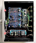
Also, yes, you can add additional boards to the diyaudiostore chassis -- I have added a +24/+15/-15 board which draws power from the stock +24V wall wart and puts that through P089ZB filters for each of the three voltages, AND a utility board which uses relays to switch inputs and delays output connection as well as provides a 12V trigger for an amplifier. It's all a tight fit, but it works.
Presently I'm using the B1K chassis to play with Wayne's BA2018 preamp board which is why the picture is of the BA2018, but the B1K is going back in shortly along with the 3-voltage filtered power supply board which is actually somewhat smaller than the power supply board shown because the converter is much smaller. The power board has relays for power up surge because I found the standard wall wart would shut down once or twice during power up due to large quantities of capacitance in the system.
Attachments
I've built this amp for a friend who has a Hypex NCore poweramp. He used it a few weeks but when he turned it on recently (with his NCore still on) there was a loud sound coming form his speakers and his poweramp was dead. It turns out both NCore modules are fried.
Is there any chance this the power-on thump could have caused this? Everything seems ok and right within specs.
Is there any chance this the power-on thump could have caused this? Everything seems ok and right within specs.
I was concerned by the pretty powerful turn-on thump, and added a turn-on delay relay to my B1K. But it doesn't seem likely to cause a failure of the power amp, more likely to cause a failure of the speaker attached to the power amp . . .I've built this amp for a friend who has a Hypex NCore poweramp. He used it a few weeks but when he turned it on recently (with his NCore still on) there was a loud sound coming form his speakers and his poweramp was dead. It turns out both NCore modules are fried.
Is there any chance this the power-on thump could have caused this? Everything seems ok and right within specs.
Thumps or voltage spikes can fry input stages, sensitive components like JFETs etc. This happened to me once with an ACP+ connected to an iphone. I forgot to turn down the volume before disconnecting because of an incoming call. I fried a precious JFET from Papa himself upon reconnecting the shitty phone.I've built this amp for a friend who has a Hypex NCore poweramp. He used it a few weeks but when he turned it on recently (with his NCore still on) there was a loud sound coming form his speakers and his poweramp was dead. It turns out both NCore modules are fried.
Is there any chance this the power-on thump could have caused this? Everything seems ok and right within specs.
anywz, that phone is never going near my gear again. But the error, like in your friends case, is a typical F40 error. Not the Ford, but as in the error is 40 centimeters from the amp (us/gremlins).
If you are absolutely certain the amp is fried, and certain that it happened when turning on the B1K, then I guess Bob’s your uncle. I wouldn’t feel at guilt for building it for him. It is not a recommended way to go about treating ones gear, be it with or without thumps.
OTOH, here is a great opportunity for your friend to leave class D and join the fearless gang 🙂
regards,
Baby V
Last edited:
Friends, I just wanted to chime in with a discovery for the green at horn tonight.
in previous posts, I advocated that going for 14V+ on the B1K into the Aleph J, iow serving the poweramp more neg sugar, then inverting @ speakers to achieve pos neg phase, was a good combo. Well, some weeks have passed, some experimentation along the way. And tonight I fired up my trusty HP siggen, and used my Tektronix 30mhz scopes FFT to discover that @ 14V5 @ T7/8, this preamp is 3rd dominant. @ 18V6 however, I achieved the equivalent amount of neg phase 2hd that I measured @ 9V5 (spec).
Just a chime for those using amps allready neg thd loaded. Worth trying. More upfront, a bit less relaxed and harder to fall asleep below 90db in the listening seat, more crowded but cool soundstage, a tad more detail, and just as musical.
Sorry for the missing porn. Viking glory days are long gone anywz.
Regards,
Andy
Hello everybody.
After a Ba3 Front End, I decided to build B1 With Korg preamp, I'm very happy with your performance, I was not expecting it to be so good.
As we are never satisfied, I wanted to provide energy to B1 / Korg with 12 V + 12V lead batteries, but I checked that both in series adds 25.5V.
Is there any way to correct this or will it be a waste of time?
Now I'm using a Wall Wart.
Thanks.
P. Dias

Goddamn, that’s gonna end in some serious sugarcane with your AJ’sOops. God damnit. Well. Oh yeah!!! 🤗

- Home
- Amplifiers
- Pass Labs
- B1 with Korg Triode