Also, if anyone has any suggestions on a good solid state preamp to build, I want something dynamic and clear. Not too concerned about the harmonic distortion. I like the voicing of the F6 already.
Thanks!
Wayne Colburn's BA2018 is what you are looking for. I replaced my B1K/F6 with the BA2018/F6 and can't go back. Excellent line amp.
Awesome, I found it:
Wayne's Burning Amp 2018 Linestage – diyAudio Store
Thanks! I will give it a look through.
Wayne's Burning Amp 2018 Linestage – diyAudio Store
Thanks! I will give it a look through.
The Nutube has a finite life, it's likely best if you power it on when using it, and off when you are not.
+1 🙂
Anybody know what this problem is and how to fix it? I run a battery powered hybrid power amp with the B1K as preamp and a Bottlehead Quicksand as the amp. I designed it to work with a DAP and it usually functions perfectly. A couple times I forgot to unplug the charger from the DAP. This results in the craziest digital distortion/feedback/weirdness that I have ever heard; sometimes sounds like R2D2 getting tortured. Same thing happens if I connect a different source that is powered via mains.
Both boards +/- are combined at a terminal strip and then goes to the battery. There is no case ground. I am guessing there is some insane ground issue occurring only when a source is connected to mains.
Both boards +/- are combined at a terminal strip and then goes to the battery. There is no case ground. I am guessing there is some insane ground issue occurring only when a source is connected to mains.
Attachments

@ Irishpatrick33
To play preamplifier music nicely better use metal chassis without air vents but all sides closed box.
For example :B1 with Korg Triode
To play preamplifier music nicely better use metal chassis without air vents but all sides closed box.
For example :B1 with Korg Triode
If you switch your amplifier on after the Nutube is powered up, and the amplifier off before the Nutube is powered down, the thump is not an issue. 🙂
Simple, no extra costs or design and it works…just sayin’..just wait till the amp’s caps are drained of voltage a bit before turning off the Nutube preamp ;>)
All this talk about the NuTube wearing out has gotten me thinking. I took some measurements of my speakers the other day and there was a 10db roll off from about 2k to 20k. I just bypassed the B1 Korg going straight from my DAC to a F6 that is my main amp. I notice that the highs came back, music is more dynamic etc...
Do the interconnects between your B1K and your F6 have high capacitance / are they long, etc.? With the 170 ohm output impedance of the B1K this might not be an issue, but it's what came to mind when you described a low-pass filter phenomenon.
Simple, no extra costs or design and it works…just sayin’..just wait till the amp’s caps are drained of voltage a bit before turning off the Nutube preamp ;>)
Consistency is the last refuge of the unimaginative - Oscar Wilde
This perspective of accepting less-than-optimal performance runs counter to the spirit of this website and the people who frequent it as well as, it seems, your own signature line. I would like to make my B1K more convenient and better behaved; why object to that?
@ Irishpatrick33
To play preamplifier music nicely better use metal chassis without air vents but all sides closed box.
For example :B1 with Korg Triode
Thanks, but this is not the problem. Everything works fine when connected to a DAP that is not charging, despite it being a vented chassis. I don't think the B1K or the Quicksand is the issue. I suspect it is my overall topology and the grounding, or lack thereof.
Boyz, you're overengineering it
no tube is made to be constantly on, same as it isn't made for often cycles of powering on and off
also, as tube doesn't care for decreased anode voltage, it does care about heater voltage being lower than declared in datasheet - practically all tubes form Yore were made to be happy with +/-10% fluctuation of heater voltage , being direct result of mains fluctuation
so, in short - if you know that you don't need your KB1 in next hour or so - power it down; you'll prolong its life .......
Could you restate what you mean by "doesn't care" and "does care" -- maybe it's the inconsistent use of "for" after "doesn't care" versus "about" after "does care" that's confusing me.
Are you saying that anode voltage is, or is not, important?
If the Korg doesn't have a heater why do I need to consider heater voltage? Or does the Korg cathode voltage take the place of heater voltage in this context?
My general thinking is that I would leave the FETs permanently powered and deal with the Korg anode and cathode voltages in the best possible way including perhaps only reducing cathode voltage rather than cutting it entirely. And I gather from reading that ideally the anode voltage should be removed before the cathode voltage is reduced or removed. Have I got that right?
Pass DIY Addict
Joined 2000
Paid Member
I no longer remember where I found this graph and others who have been doing tube stuff far longer than I have say they remember this kicking around for a very long time.
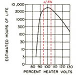
Nevertheless, here it is - a graph of tube life vs filament voltage levels. The plus/minus 5% dotted lines are my addition. Take it for what it's worth...
Nevertheless, here it is - a graph of tube life vs filament voltage levels. The plus/minus 5% dotted lines are my addition. Take it for what it's worth...
Attachments
Nevertheless, here it is - a graph of tube life vs filament voltage levels. The plus/minus 5% dotted lines are my addition. Take it for what it's worth...
Interesting. You caused me to go back to the Korg Application Note and read it again. It appears that the Korg tube cathode/heater is specified at 17ma current, and a resistance of 41R. Ohms law -- if the supply is 9.1V to generate 17ma then total resistance should be 535 ohms. If the tube is 41 ohms then the load resistor should be 535-41=494R, but the App Note suggests 475 which is the resistor supplied with the kit. With a 9.5V zener instead of the nominal 9.1V the current rises to 18mA which should be fine.
But wait, there's more!
Here is a really informative discussion of constant current sourcing of heater versus constant voltage. The inrush current of constant voltage through a low-resistance cold heater is far greater than the steady state current after the heater has reached operating temperature and that, I suppose, is why you should not switch tubes on and off excessively.
Constant Current for Tube Heaters. Extend the Life of Your Amplifier’s Vacuum Tubes | audioXpress
Which suggests to me that an LM317 plus one resistor to replace the 475 ohm resistor to change the circuit to precision 17ma constant-current would prolong the tube by avoiding the inrush current associated with turning the tube on. Surely that would help with longevity?
Here is a graph depicting the difference in turn-on behavior of a tube heater -- constant current vs constant voltage. The B1K is a constant voltage.
The recommendation to keep a tube heater at half-power when the equipment is OFF rather than turning it completely off must be due to the fact that the surge will be much less if the heater is already partially warmed up when the turn-on surge arrives.
The recommendation to keep a tube heater at half-power when the equipment is OFF rather than turning it completely off must be due to the fact that the surge will be much less if the heater is already partially warmed up when the turn-on surge arrives.
Attachments

Last edited:
Black PCBs are an option that you can select, on the wonderful website
www dot pcbshopper dot com
Just now I did this, and received price quotes from seventeen different PCB fabs, to build qty=10 of 2-layer black PCBs. The cheapest price quote came from the fab named JLCPCB, and the most expensive was from Bay Area Circuits.
BTW the photos I showed in this thread, of black front panel and black rear panel PCBs, are actually a product which is sold by the diyAudio Store. Have a look at the photos attached to its sales page. Scroll down just a little bit to see thumbnail images of the available photos, then click on whichever ones you want to see full size.
Ah, clever! I now see them on the sales page.
Pass DIY Addict
Joined 2000
Paid Member
The recommendation to keep a tube heater at half-power when the equipment is OFF rather than turning it completely off must be due to the fact that the surge will be much less if the heater is already partially warmed up when the turn-on surge arrives.
Curious - given the graph above, I don't think I'd want to keep any heater at 50% power. My interactions with Jac at EML seems to fit the graph pretty well - he indicated that his 300B tubes will tolerate a pinch (maybe 3-4%) of over-voltage far better than a pinch of under-voltage. He claims to be able to identify an under-voltage filament through visual inspection of the damaged filament.
I do understand the idea of start up vs steady-state power draw, though. This is pretty much why incandescent light bulbs mostly blow when you first turn them on, not after they are already lit.
Last edited:
Curious - given the graph above, I don't think I'd want to keep any heater at 50% power. My interactions with Jac at EML seems to fit the graph pretty well - he indicated that his 300B tubes will tolerate a pinch (maybe 3-4%) of over-voltage far better than a pinch of under-voltage. He claims to be able to identify an under-voltage filament through visual inspection of the damaged filament.
I think the secret of the half-power is that the filament never gets cold, so the initial surge is much reduced because the filament already has considerable heat-dependent resistance going when full power is applied. Since the rest of the tube -- anode, grid -- are OFF when the heater is at half power, the half-power does not harm the heater or the tube. I think. Still don't know much about tubes . . .
Half power on B+/anode, not filament/heater
I have not seen any design that puts heater/filament voltage at half "power" during periods of inactivity.
There ARE designs that put the B+/anode voltage at half/reduced voltage during standby, for several reasons. One is to protect against cathode stripping until the filament/heater comes to full temperature; this is relevant, as I understand it, only for power tubes and not low signal tubes. Another is to protect the capacitors in the power supply against over-voltage during the initial turn-on, or from fuses burning out due to the big current surge at initial turn-on. The use of an inrush current limiter is often used in this manner: I've seen a Scott and Marantz tube design use the thermistor in this fashion.
In view of the data on tube life versus heater voltage, as well as the lack of design precedent, it does not seem a good design decision to adopt a half-voltage standby approach for heaters/filaments.
Note that Mark Johnson's approach was using 50% B+/anode voltage as one of his settings in his 4-position switch scheme, if I understand his suggestion.
I have not seen any design that puts heater/filament voltage at half "power" during periods of inactivity.
Note that Mark Johnson's approach was using 50% B+/anode voltage as one of his settings in his 4-position switch scheme, if I understand his suggestion.
I'm not going to play with the half-power idea.
Right now I'm leaning toward simply removing the cathode resistors and replacing them with LM317Ls and a resistor to set current to 17mA. This doesn't affect operation but does protect against power surges at turn-on. I can get the TO-92 and resistor in a compact assembly to fit in the existing resistor space. That, together with an output delay relay will make me comfortable with the Korg, and a 12V trigger circuit will allow the Korg to control my power amp. I'll feel comfortable turning the system on and off more frequently, and also feel secure that an output relay will instantly disconnect the Korg from the power amp if there is a power problem that might send a large pulse down the line.
Last edited:
Constant current is the way to go
Assuming that one is willing to accept the inherently greater complexity (in terms of both design and troubleshooting) and cost, it would seem that constant current on the heater/filaments is to be preferred over constant voltage. There were several Audio Amateur/Glass Audio/AudioXpress articles over the decades by different authors which all advocated the constant current approach as opposed to simple voltage regulation.
Something that I have never seen done is to put an inrush current limiter on the heater/filament line to reduce inrush current. The downsides to this possible approach are: (i) transformer must be rated to take the increased current draw dissipate in the inrush current limiter; (ii) more heat generated under the chassis which must be dissipated; (iii) space to fit this in; and (iv) the difficulty of finding the correct value of limiter to ensure that the +/- 10% limitation is met during operation. Perhaps someone can comment on this approach.
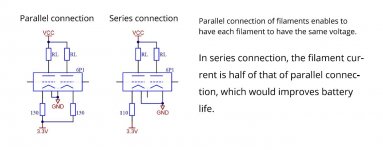
The B1K schematic shows that the two Korg cathodes are wired in parallel with separate current-limiting resistors and smoothing capacitors. Is there any operational (audible) reason that they cannot or should not be wired in series with a single 17mA constant-current source? I think the Korg Application Note schematic has an error -- the "series" connection doesn't look right.
Attachments
Last edited:
- Home
- Amplifiers
- Pass Labs
- B1 with Korg Triode